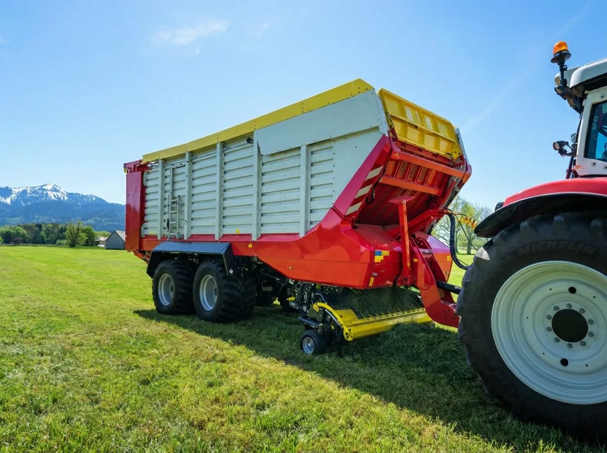
Pöttinger forage wagon
A Pöttinger forage wagon with no ISOBUS of its own. Eight outputs cover the pickup, the boom, the rear door, the conveyor floor and the buzzer. Two sensors on the digital inputs take the floor over while you load and unload, on one button you arm from the armrest.
- Outputs
- 8of 8 used
- Module
- 1×ISOBUS Block 8-channel
- Inputs
- 2sensors on the digital inputs
- Control
- AUX-Nor from the tractor screen
Wire it
Every channel wires the same way. Battery positive taps the COM screws in use; each NO goes out to one load, and the load returns to chassis ground.
All eight outputs in use. The two sensors land on the module's own input header, not on the ISOBUS connector, and a sensor that signals with +12 V needs the input COM tied to ground.
| CH | Icon | Name | Function | Mode |
|---|---|---|---|---|
| CH1 | PICK + | Pickup raise | MOM | |
| CH2 | PICK - | Pickup lower | MOM | |
| CH3 | BOOM + | Boom raise | MOM | |
| CH4 | BOOM - | Boom lower | MOM | |
| CH5 | DOOR OP | Door open | MOM | |
| CH6 | DOOR CL | Door close | MOM | |
| CH7 | FLOOR | Conveyor floor | TOG | |
| CH8 | BUZZER | Buzzer | MOM |


Name it
One button on the terminal is a name, an icon, the outputs it switches, and MOM or TOG. That is all there is to set up. No laptop, no software.


Drawing of the ISOBUS UT screen, not a screenshot.
The button editor as it appears on the tractor screen. Names are capped at 8 characters.
Drive it
The finished dashboard. Press the buttons here on the screen, or assign the same functions to armrest or joystick buttons through the tractor's AUX-N menu. Both work side by side.


Drawing of the ISOBUS UT screen, not a screenshot.
Drawn from the channel map above, not a photograph of an installation.
Let the sensors do it
Each sensor gets one rule: what it drives, and what counts as active. You arm the rule from the terminal or from an armrest button, and it stays armed until you disarm it or take manual control.
The sensors are optional. Everything above already works from the buttons on their own, and plenty of machines are wired with the inputs left empty. Add them when you would rather not hold a button while you watch something else.
| Input | Sensor | Mode | Drives | Armed by |
|---|---|---|---|---|
| DI1 | Level sensor | FOLLOWOutput on while input active | CH7 | AUTO |
| DI2 | Door sensor | FOLLOWOutput on while input active | CH7 | AUTO |
One tile arms DI1 and DI2 together, so it is one AUX-N assignment and not one per sensor. A tile takes a name and an icon exactly like a relay button does. Nothing arms itself: not at power-up, not after a preset change, not when the terminal reconnects. Touch a manual control that overlaps an armed tile and it drops out on the spot, and it never comes back on its own. This is protection for normal operation, not a safety function.
Variations
The same machine, wired differently.
Knife bank as well
Where the knife bank swings out on its own valve, that is two more outputs and the eight are already full.
10 outputs · 2× 8-channelLimit switches on the door
Two end switches wired normally closed, set to INVERT and BLOCK, so a broken wire stops the automation instead of quietly removing the limit. Manual control is untouched.
8 outputs · 4 inputsWhat you need
- 1×External Connector Kit€75Contacts ship loose, you crimp them
- 1×Weatherproof enclosureyour own. The bare module is IP20, so it needs one on an implement
- 2×Sensors, 5 to 36 Vyour own, and optional. Dry contact, NPN or PNP all work
- Two-core cable to each solenoidyour own
Now do yours
Same module, same three steps. What you wire to the channels is up to you.
Questions
Will this work on my tractor?
Any ISOBUS tractor with a Virtual Terminal, whatever the make. The in-cab ISOBUS connector is the same on every brand, so there is nothing to match to yours.
Do I need a weatherproof enclosure?
Outdoors, yes. The bare module is IP20, which means in-cab or panel mounting only, so on an implement it goes in a weatherproof box you supply yourself.
Can I change the button names and icons myself?
Yes, from the tractor screen. A button takes a name of up to 8 characters and an icon from the module's set, and both show up in the tractor's AUX-N assignment menu as well. The WiFi interface is for diagnostics, testing outputs and firmware, not for setup.
What if the machine needs more than 8 outputs?
There is a 32-channel module: one unit with 32 relay channels, everything else the same. It has no digital inputs, so a machine that also needs sensors takes a second 8-channel module instead.
More machines
Pöttinger is a trademark of its owner. ISOBUS Block is not affiliated with it, and this page is not endorsed by it.