A customer's Fendt 724. The module in a weatherproof box bolted under the cab. Full wiring on the use-case page.
A customer's Fendt 724. The module in a weatherproof box bolted under the cab. Full wiring on the use-case page.
A custom build, shown for reference. The standard module is the bare unit; this box, its wiring and its connectors were built to order.
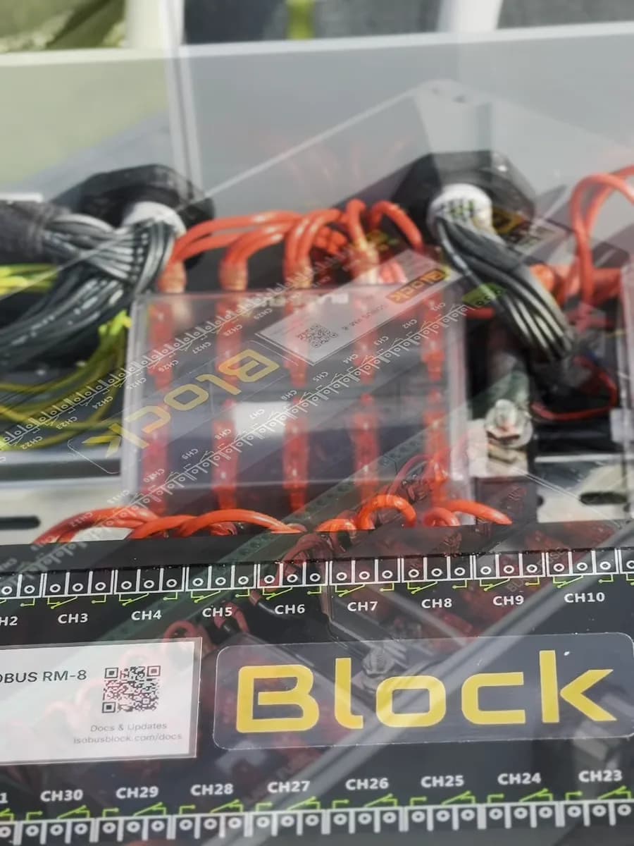
Inside the same build: module, fuse block and output wiring done before shipping. On the standard module, this is the part you wire yourself.
Each lead ends in the connector the machine needs. This build uses Deutsch connectors and 3-pin sockets, plus a plug for the in-cab ISOBUS socket.
Twin-rotor rake control box on the armrest
ISOBUS Block on the rake switches the rotor lift and the working width from buttons on the tractor armrest and screen.
ISOBUS Block 8-Channel Relay Module
Free shipping on all orders, via DHL Express.
Any import tax and duty are paid on delivery.
Returned complete and undamaged. Buyer pays return postage. Custom kits excluded; faults covered by the 5-year warranty.
Payments by Stripe · Visa, Mastercard, Apple Pay, Klarna
Not sure it fits? Check in 30 sEach rotor from the armrest
A twin-rotor rake on an external controller runs from its own box in the cab.
With ISOBUS Block on the rake, each rotor's lift and the working width get buttons on the tractor screen, and the rotor lifts go on armrest buttons.
Wiring the rake to the module
- Mount the module in an enclosure on the rake's frame, near the hitch.
- Connect the old controller's leads to relay outputs.
- Plug the rake into the rear ISOBUS socket through an ISOBUS cable and the External Connector Kit's plug.
- Name a button for each rotor, for example ROTOR L, and assign the rotor lifts to the armrest.
What you need
- ISOBUS Block 8-channel module.
- External Connector Kit. The plug for the rear ISOBUS socket, with the module on the rake.
- ISOBUS cable in 3 m (10 ft), 6 m (20 ft) or 10 m (33 ft).
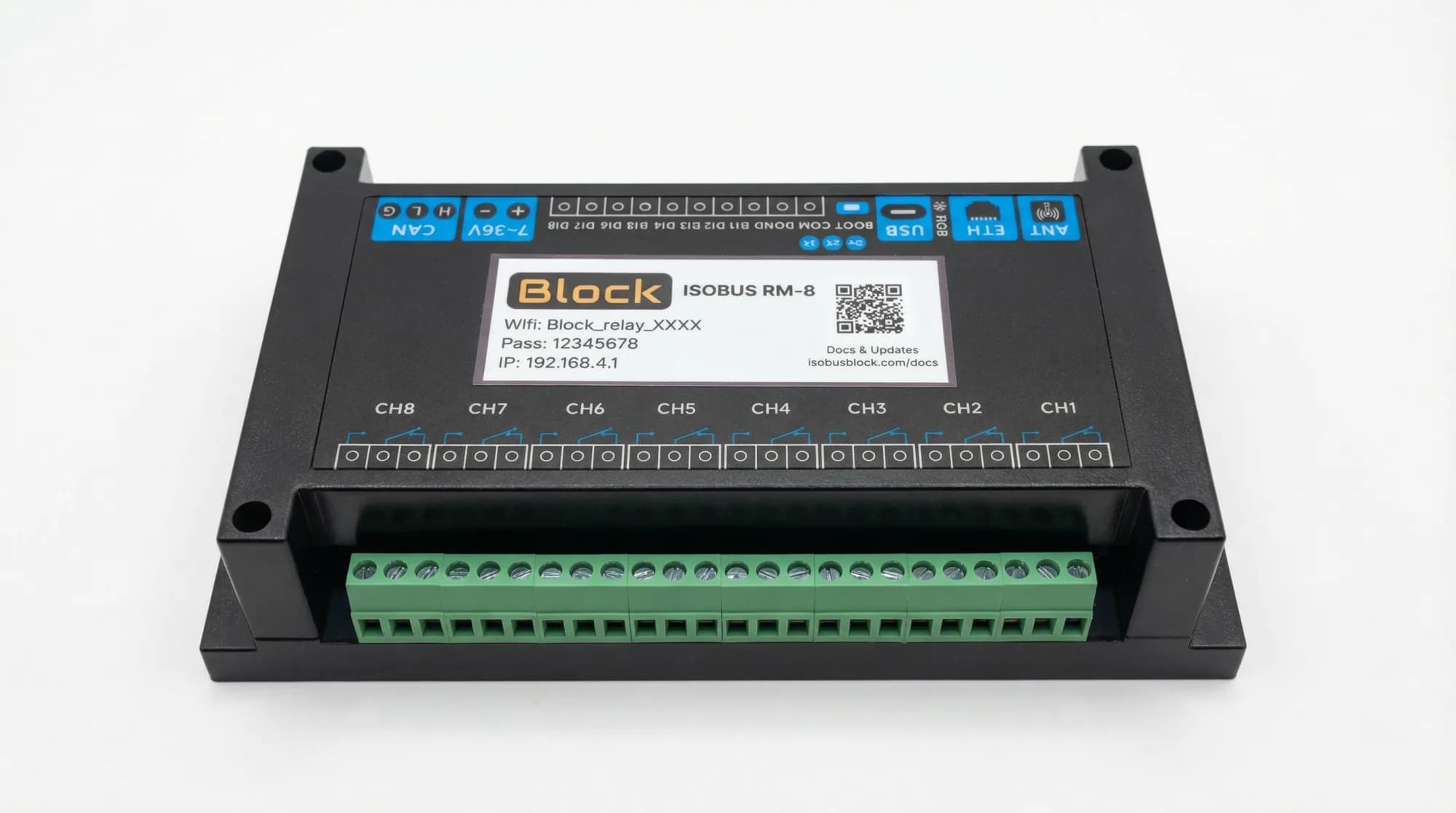
8 × 10 A
Relay channels, NO, COM and NC terminals on each
8 Outputs on Your Joystick
Pick a button, pick an output, done. Assignments stay in the tractor.
Custom Names & Icons
Name each channel, pick an icon. Both show on the screen and in the joystick menu.
Toggle or Momentary
Toggle stays on until you press again. Momentary runs while you hold. Set per channel.
Group Channels Together
One press, several relays. Open a valve and switch on a work light together.
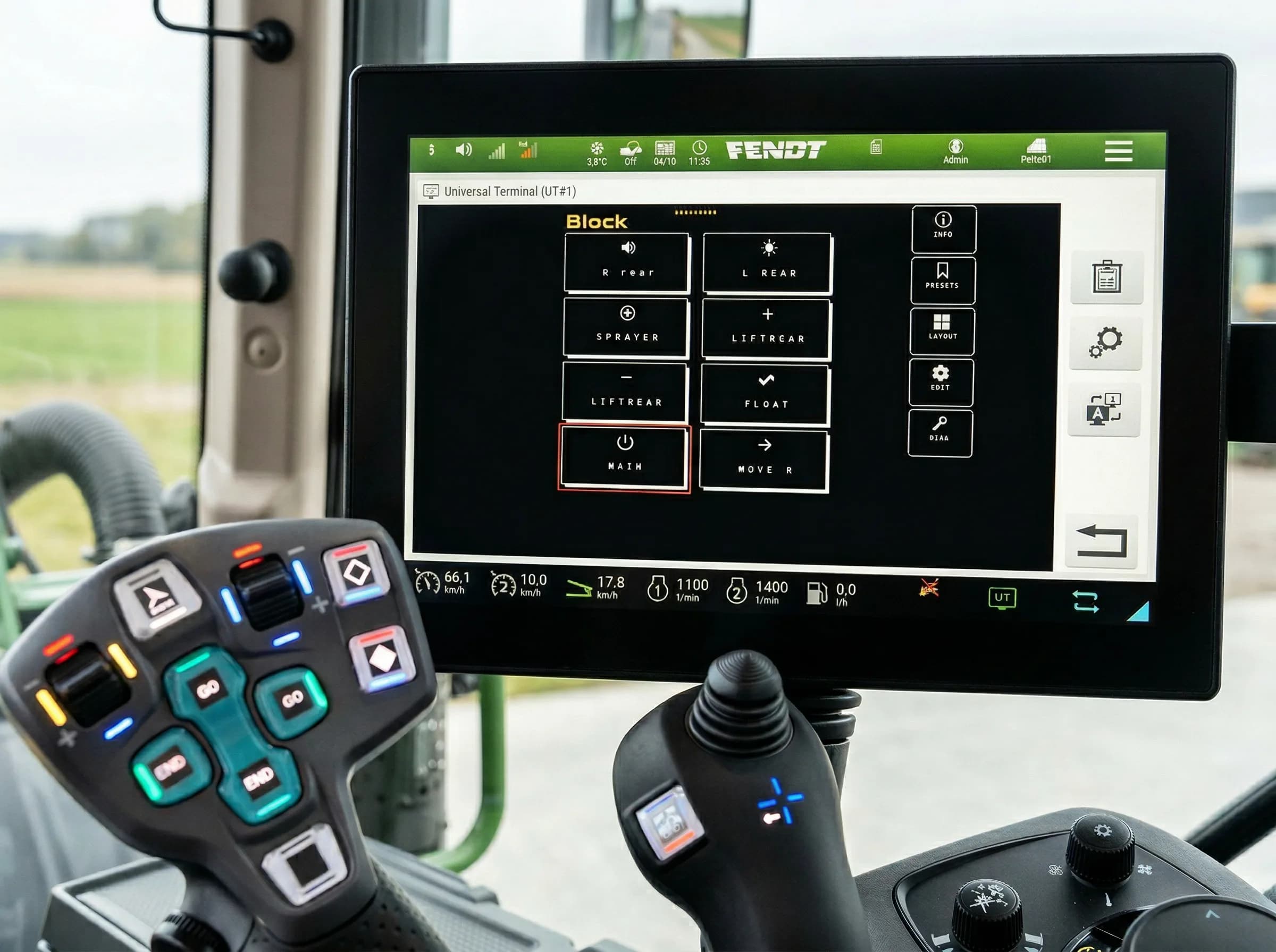
Your screen
Buttons named, icons picked, on the terminal you already have
On customers' machines
A customer's machine: an Amazone Pantera being converted from a sprayer into a harvesting machine. A 32-channel build switches its new functions.
A hook-lift trailer in the UK, fitted by our dealer Tramline Tec. The 32-channel module in an enclosure on the chassis. We ship the module only; the box, terminals and wiring are the installer's.
A customer's Fendt 724. The module in a weatherproof box bolted under the cab. Full wiring on the use-case page.
A customer's potato trailer in the UK. The 8-channel module in an enclosure on the trailer replaced the switch box in the cab.
What customers tell us
It was a pleasure to work with you, very knowledgeable and nothing too much of a problem. Great piece of ingenuity.
A customer in Austria fitted the module to a new Fendt 724 and wired six channels to the 15-pin socket for a three-way tipper, with two spare in the cab. He wrote that the install was plug and play and that controlling the tipper from the terminal is comfortable.
Austria. Fendt 724 Gen6, three-way tipper with lift axle.
Excellent customer service. The rake worked really well all season, much easier steering with the ISOBUS Block installed.
Name it. Assign it. Press it.
Mount it, wire your loads, plug in one ISOBUS cable, and set up your buttons on the tractor screen. A screwdriver does the module end.
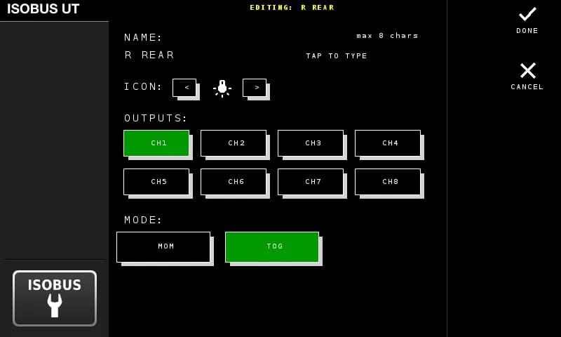
Name your button
Type a name (up to 8 characters), pick an icon, select which outputs it controls, and choose toggle or momentary mode.
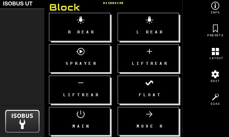
See it on the screen
Your buttons show up on the tractor display with the names and icons you chose. Pick a layout that fits your setup.
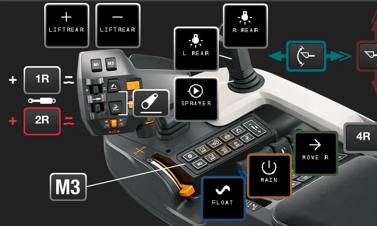
Assign to your joystick
Open the tractor's AUX-N menu. Your named buttons appear there. Assign them to any joystick or armrest button you want.
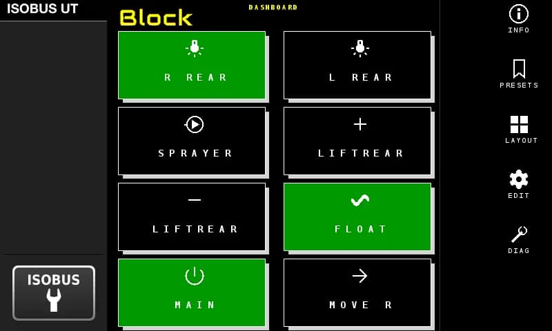
Press it
Your joystick button switches the relay. Active outputs light up green on the screen. That's the whole system.
What actually changes
Same tractor. Same cab. Completely different setup.
- Drilling holes, mounting switches
- Clean cab, no modifications
- Relay boards, fuses, wiring looms
- One ISOBUS cable, done
- Hard-wired, can't change it
- Reassign any output from the screen
- Reaching across the cab for switches
- Everything on your joystick hand
- Which switch was the work light again?
- Labels on the tractor display
Description
AUX-N Control
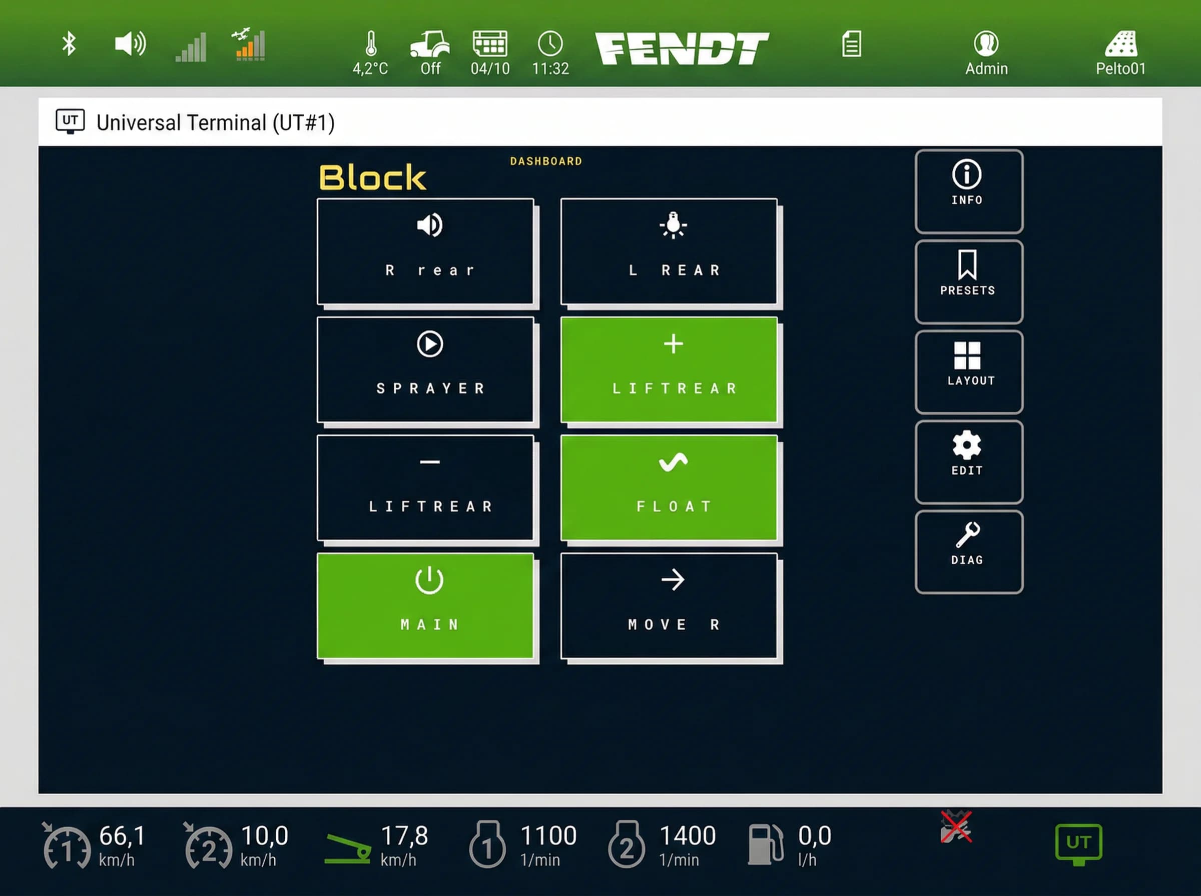
The module's buttons on a Fendt terminal
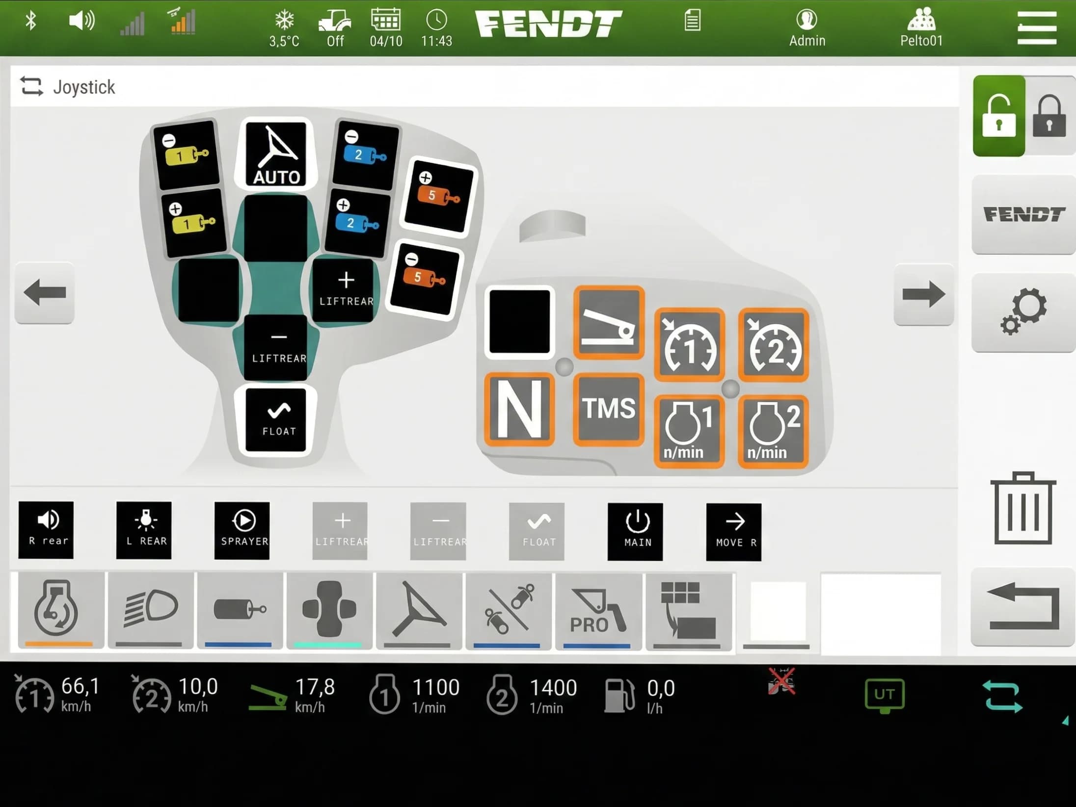
The same buttons on the Fendt AUX-N assignment page
See it in action
The actual screens you'll use: button editor, layout options, AUX-N assignment, and more.
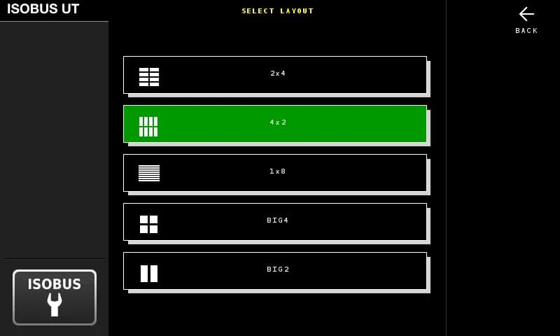
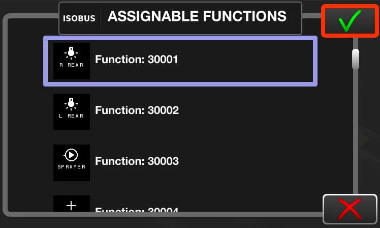
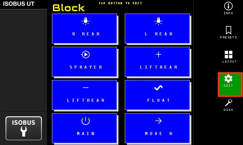
Control outputs from the screen too. Five button layouts to choose from
Let a sensor do the switching
The module has 8 digital inputs. Wire a proximity sensor, a limit switch, a pressure switch or a cab panel switch to one, and it switches the relay outputs for you. 5 to 36 V, optocoupler isolated, for dry contact, NPN and PNP sensors.
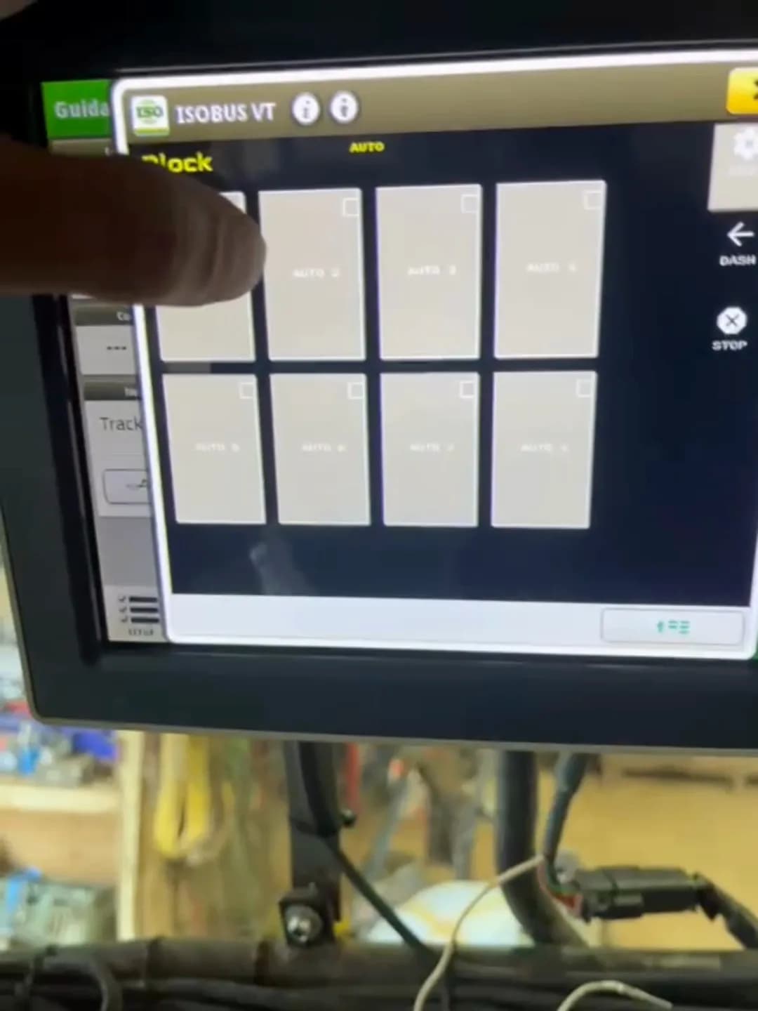
You decide when it runs: arm it from the tractor screen or from an armrest button. Everything is set up on the terminal. No laptop, no app, no programming.
How the inputs work
Output on while the input is active.
A sensor on the wagon door. When the load pushes the door open, a buzzer sounds in the cab.
Each pulse flips the output on or off.
Forces the outputs off while the input is active.
For an end switch or a limit switch. It stops the automation, never your own button press.
Manual always wins
Grab the joystick and the automation drops out. Any joystick, armrest or screen button that overlaps a running function disarms it. The automation never blocks, limits or delays what you do by hand.
- Automation never resumes by itself. Re-arming is one deliberate press.
- Nothing arms itself. After a power cycle everything is manual again.
- A latched STOP holds every output off until you release it. It is an operator control, not an emergency stop.
Tune each input to the machine
Five settings per input, stored per preset. A live IN and OUT indicator on the same terminal page shows the raw sensor next to the filtered result.
| Setting | What it does | Range |
|---|---|---|
| Debounce | Filters contact bounce and electrical noise. | 10 ms to 1 s |
| On delay | The sensor has to mean it before anything moves. Ignores bumps and blips. | 0 to 10 s |
| Off delay | Stops hunting when a sensor sits right on its trigger point. | 0 to 10 s |
| Min on | Once on, the relay stays on at least this long, so a twitchy sensor cannot chatter it and wear it out. | 0 to 10 s |
| Max on | Ceiling on continuous on-time. Catches a sensor that fails stuck-on. | No limit, or 1 to 300 s |
Hard floors of 100 ms on and 100 ms rest are built in. No combination of settings can chatter a relay from the input side.
What it is not
This is not a safety system. Block inputs and interlocks stop the automation, not you. If a movement has to stop whatever happens, fit a mechanical end stop.
An input is on or off. It does not measure a level, count pulses or read a frequency. Two inputs can be interlocked so they never run at the same time. That is the only logic between them.
The web interface only tests outputs and updates firmware. Switching an output there turns all automation off.
Built for the field
8 relay channels, 10A each, 7–36V input. Set up everything from the tractor screen.
| Supply voltage | 7–36V DC |
| Relay channels | 8 (NO, COM, NC per channel) |
| Max current | 10A per channel |
| Max switching voltage | 30V DC / 250V AC |
| Protection | Optocoupler isolation, power isolation |
| Enclosure | Rail-mount ABS housing (indoor use; requires weatherproof enclosure for outdoor installation) |
| Dimensions | 90 × 175 mm |
| Weight | 500 g |
| Operating temperature | −30°C to +50°C |
| Warranty | 5 years |
Optional add-ons
Connector kits and cable
Where you mount the Block decides the connector. In the cab, it plugs into the tractor's in-cab ISOBUS socket. On the implement, it plugs into the external socket at the rear or front, and the ISOBUS cable runs from there to the Block.
None of these are required. The module takes any ISOBUS cable you source yourself. The kits and the cable just save you sourcing the parts.
Add them next to Add to cart at the top of this page.
Questions?
More from the ISOBUS Block platform
ISOBUS Block, built to order
Tell us the machine and what you want it to do. We work out the rest and build it here.
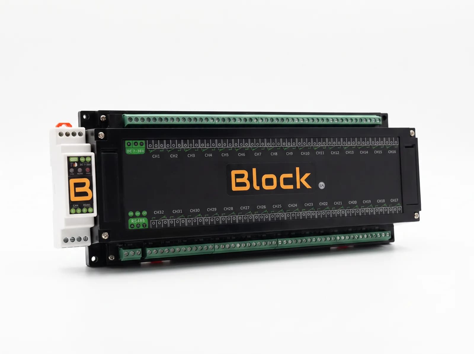
ISOBUS Block 32‑Channel Relay Module
When eight outputs are not enough. 32 relay channels, 10 A each, controlled from the tractor screen and the AUX-N buttons you already have.