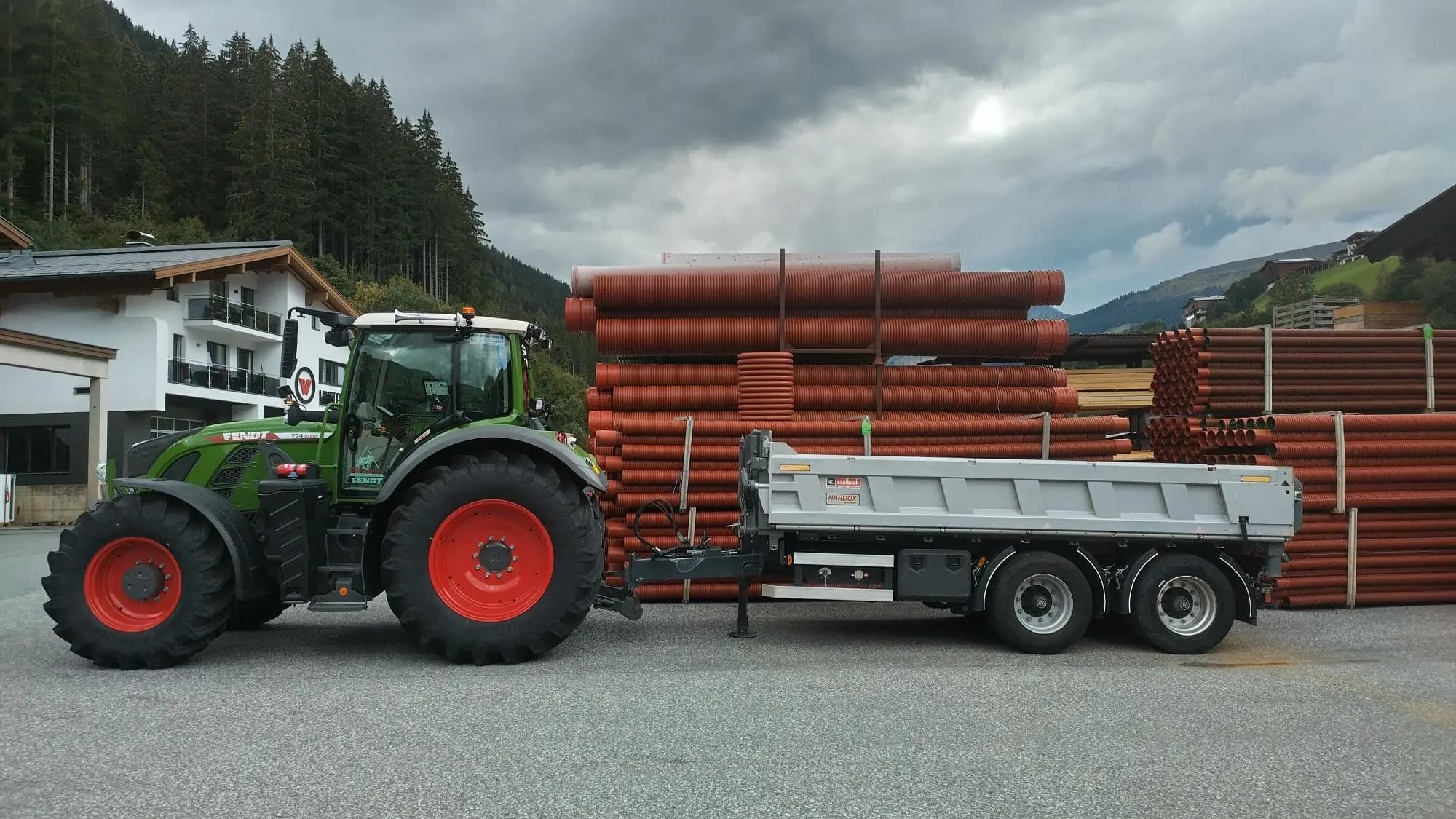
Add relay outputs to a modern tractor (Fendt 724 install)
A Fendt 724 gained eight programmable relay outputs it didn't have from the factory, wired and named like any other AUX-N function on the terminal. Six of them land on a new 15-pin ISO 12098 socket at the rear, so any implement wired to match can plug in and get working controls straight away. The other two stay in the cab, and each implement gets its own preset, so swapping to the next one is a preset change on the terminal, not a rewire.
- Outputs
- 8of 8 used
- Module
- 1×ISOBUS Block 8-channel
- Inputs
- Noneno sensors needed
- Control
- AUX-Nor from the tractor screen
One of our customers built this install and cleared us to publish the photos. The photos show a weatherproof enclosure bolted neatly under the cab, colour-coded relay leads out through the bottom glands, the four buttons in the tipper preset named on the terminal, and three Block functions dropped onto the joystick. Careful, tidy work. Thanks for the photos. Real installs are the best way to show how this actually goes together. If you have installed a Block on your own machine, we would love to feature it here too. Get in touch.
Wire it
Every channel wires the same way. Battery positive taps the COM screws in use; each NO goes out to one load, and the load returns to chassis ground.
All eight channels are wired. Two stay in the cab (CH1 horn, CH2 spare); six run out to the new 15-pin ISO 12098 socket at the rear. Both trailer functions today (CH7 axle lift, CH8 6/2-way sidewall shift) run MOM.
| CH | Icon | Name | Function | Mode | Cable | Destination |
|---|---|---|---|---|---|---|
| CH1 | HORN | Air horn | MOM | Blue 5×2.5 mm² | Cabin horn relay | |
| CH2 | CAB RES | Cabin spare | MOM | Grey 5×2.5 mm² | Cabin (spare, unassigned) | |
| CH3 | RES | Trailer spare | MOM | Green | 15-pin trailer socket, pin 13 | |
| CH4 | RES | Trailer spare | MOM | Blue | 15-pin trailer socket, pin 12 | |
| CH5 | RES | Trailer spare | MOM | Violet | 15-pin trailer socket, pin 8 | |
| CH6 | RES | Trailer spare | MOM | Orange | 15-pin trailer socket, pin 9 | |
| CH7 | AXLE + | Lift axle up | MOM | Grey | 15-pin trailer socket, pin 10 (axle lift) | |
| CH8 | TAILGATE | Tailgate (6/2-way shift) | MOM | Yellow | 15-pin trailer socket, pin 11 (sidewall 6/2-way shift) |


Name it
One button on the terminal is a name, an icon, the outputs it switches, and MOM or TOG. That is all there is to set up. No laptop, no software.


Drawing of the ISOBUS UT screen, not a screenshot.
The button editor as it appears on the tractor screen. Names are capped at 8 characters.
Drive it
The finished dashboard. Press the buttons here on the screen, or assign the same functions to armrest or joystick buttons through the tractor's AUX-N menu. Both work side by side.


Drawing of the ISOBUS UT screen, not a screenshot.
Drawn from the channel map above, not a photograph of an installation.
From the install itself
Photos from the customer who built this.
Where the box lives: bolted to the tractor chassis under the cab.
ISOBUS supply and CAN enter through the top gland. Eight relay-side leads exit through the bottom glands.
Terminal block populated, module on the DIN rail.
Finished wiring. Red supply on the shared COM rail, one coloured lead per channel out to the socket or the cabin.
The Block feeds off the tractor’s rear external ISOBUS connector, above the drawbar.
The Hella 15-pin ISO 12098 socket, bracketed onto the rear coupling area beside the hydraulic quick-couplers.
The trailer’s mating plug clipped in.
The tipper preset on the Fendt Universal Terminal, running in BIG4 layout: four large tiles instead of the default 2×4 grid of eight, chosen so the buttons in use read at a glance from the seat. Names typed in German; the tractor stores whatever you type.
The Fahrhebel assignment page. Achslift on the top face, Horn on the upper thumb button, Klappe on the side thumb button. The tractor stores the mapping across power cycles.
From the cab: terminal, joystick, armrest.
Variations
The same machine, wired differently.
Silage wagon preset
Reuse the same six trailer-side pins. CH8 becomes Pickup, CH7 becomes Rear door, and the four reserves (CH3–CH6) take Boom raise, Boom lower, Floor forward and Floor reverse. Same Block, same socket, load the preset when you hook up.
6 outputs · 1× 8-channelMuck spreader preset
Reuse the same six pins again. CH8 becomes Beaters, CH7 becomes Floor chain, and two of the four reserves handle Work lights and Beacon. The last two reserves stay unnamed for the next thing added.
6 outputs · 1× 8-channelFeed off the in-cab socket instead
The Block runs off any of the tractor’s ISOBUS sockets. If the enclosure lives in the cab, use the In-Cab Connector Kit and route the trailer channels down to the rear socket.
3 outputs · 1× 8-channelWhat you need
- 1×External Connector Kit€75Contacts ship loose, you crimp them onto the ISOBUS lead
- 1×Weatherproof enclosureyour own. The bare module is IP20, so a tractor-chassis mount needs a box
- 1×ISO 12098 15-pin trailer socketyour own. This build uses an off-the-shelf Hella socket; any ISO 12098 socket works
- Six-core cable from the enclosure to the 15-pin socketyour own. Size it for the loads you plan to switch through it
- 1×ISO 12098 15-pin plug on each traileryour own. Wire it to the trailer’s solenoids per the preset you plan to load
Now do yours
Same module, same three steps. What you wire to the channels is up to you.
Questions
Will this work on my tractor?
Any ISOBUS tractor with a Virtual Terminal, whatever the make. The in-cab ISOBUS connector is the same on every brand, so there is nothing to match to yours.
Do I need a weatherproof enclosure?
Outdoors, yes. The bare module is IP20, which means in-cab or panel mounting only, so on an implement it goes in a weatherproof box you supply yourself.
Can I change the button names and icons myself?
Yes, from the tractor screen. A button takes a name of up to 8 characters and an icon from the module's set, and both show up in the tractor's AUX-N assignment menu as well. The WiFi interface is for diagnostics, testing outputs and firmware, not for setup.
What if the machine needs more than 8 outputs?
There is a 32-channel module: one unit with 32 relay channels, everything else the same. It has no digital inputs, so a machine that also needs sensors takes a second 8-channel module instead.
More machines
Fendt and Saalbach are trademarks of their respective owners. ISOBUS Block is not affiliated with them, and this page is not endorsed by them.