In short: An ISOBUS fault code has two parts. The SPN says which component or parameter reports the problem, and the FMI says how it failed: SPN 168 FMI 1 means battery voltage critically low. The structure is the same on every brand. Stored codes can usually be cleared from the VT diagnostic menu once the fault is fixed, and active codes clear themselves.
ISOBUS fault codes appear on your tractor's Virtual Terminal when a device on the bus detects a problem. Each code tells you what failed and why. Reading them correctly is the difference between a quick field fix and a dealer visit.
What Are ISOBUS Fault Codes?
ISOBUS fault codes are standardized error messages transmitted over the CAN bus network according to the SAE J1939 diagnostic protocol. When an electronic control unit (ECU) on the ISOBUS network detects a problem (a sensor out of range, a communication failure, or a power supply issue), it broadcasts a diagnostic message containing a structured fault code.
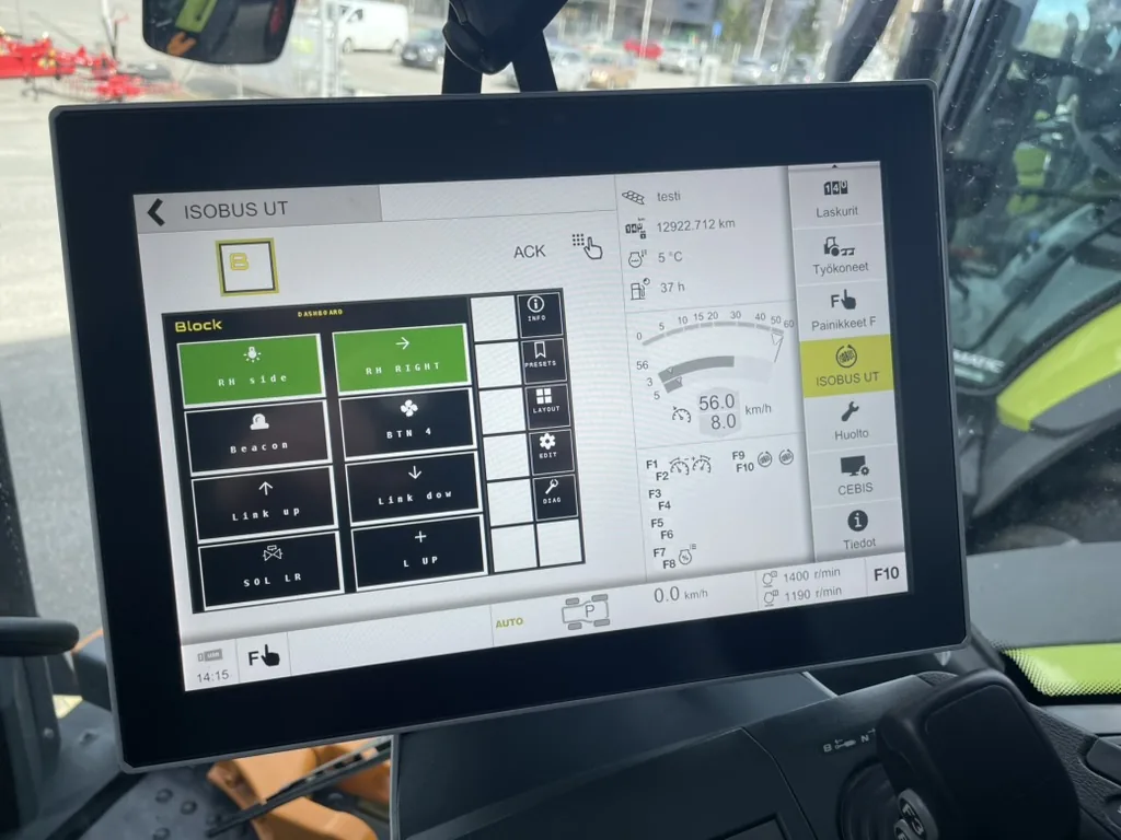
These codes appear on the Virtual Terminal in the tractor's cab, usually as part of the implement's alarm or diagnostic screen. Some tractors also log fault codes in their own diagnostic memory, accessible through brand-specific service tools.
The key thing to understand: ISOBUS fault codes follow the same structure across all manufacturers. A fault code from a John Deere implement uses the same numbering system as one from a Fendt or Case IH implement. This standardization comes from SAE J1939, the underlying transport protocol that ISOBUS (ISO 11783) builds upon.
How Fault Codes Are Structured: SPN and FMI
Every ISOBUS diagnostic trouble code consists of two parts (both terms are also in the ISOBUS glossary):
SPN: Suspect Parameter Number
The SPN identifies what is reporting the fault. It points to a specific component, subsystem, or data parameter. SPNs are defined by SAE J1939 and range from 0 to over 500,000.
Think of the SPN as the "noun" in the fault description. It tells you which part of the system is involved.
Examples:
- SPN 168: Battery voltage
- SPN 639: J1939 CAN bus communication
- SPN 2000: ECU data link
- SPN 3480: Virtual Terminal status
FMI: Failure Mode Identifier
The FMI describes how the parameter has failed. It's a number from 0 to 31 that indicates the type of failure.
Think of the FMI as the "verb". It tells you what went wrong with the component identified by the SPN.
| FMI | Failure Mode | Description |
|---|---|---|
| 0 | Data valid but above normal range (most severe) | Value too high, critical |
| 1 | Data valid but below normal range (most severe) | Value too low, critical |
| 2 | Data erratic, intermittent, or incorrect | Signal is unstable or wrong |
| 3 | Voltage above normal | Sensor or circuit voltage too high |
| 4 | Voltage below normal | Sensor or circuit voltage too low |
| 5 | Current below normal | Open circuit or broken wire |
| 6 | Current above normal | Short circuit |
| 7 | Mechanical system not responding | Physical component stuck or jammed |
| 8 | Abnormal frequency, pulse width, or period | Timing signal out of spec |
| 9 | Abnormal update rate | Expected messages not arriving on time |
| 10 | Abnormal rate of change | Value changing too fast |
| 11 | Root cause not known | Failure detected but cause unclear |
| 12 | Bad intelligent device or component | ECU internal failure |
| 13 | Out of calibration | Needs recalibration |
| 14 | Special instructions | Refer to manufacturer documentation |
| 15 | Data valid but above normal range (least severe) | Value slightly high, warning |
| 16 | Data valid but above normal range (moderate) | Value high, attention needed |
| 17 | Data valid but below normal range (least severe) | Value slightly low, warning |
| 18 | Data valid but below normal range (moderate) | Value low, attention needed |
| 19 | Received network data in error | Corrupted data on CAN bus |
| 31 | Condition exists | General status flag, active condition |
Reading a Complete Fault Code
When you see a fault code like SPN 168 FMI 1, read it as:
- SPN 168 = Battery voltage
- FMI 1 = Below normal range (most severe)
- Translation: Battery voltage is critically low
The combination of SPN and FMI gives you both the location and nature of the problem.
Common ISOBUS Fault Code Categories
CAN Communication Errors
Communication faults are among the most common issues on ISOBUS networks. They indicate that devices aren't talking to each other properly.
SPN 2000 FMI 9: Abnormal Update Rate (ECU Not Communicating)
What it means: An ECU that was previously communicating has stopped sending its expected messages within the required time window.
Common causes:
- Loose or disconnected ISOBUS cable
- ECU has lost power
- CAN bus wiring fault (broken wire, bad crimp)
- ECU has crashed or locked up
Troubleshooting steps:
- Check the physical ISOBUS connection. Is the cable fully seated?
- Verify power to the implement ECU
- Power cycle the implement (disconnect and reconnect)
- Inspect the ISOBUS cable for damage, especially near connectors and where it passes through tight spaces
- Check CAN bus termination: measure 60 ohm between CAN_H and CAN_L with system off
SPN 639 FMI 2: CAN Bus Data Erratic
What it means: The CAN bus communication link is receiving corrupted or inconsistent data.
Common causes:
- Incorrect CAN bus termination (missing or extra 120 ohm resistors)
- Electromagnetic interference from hydraulic pumps or solenoid valves
- Damaged CAN bus wiring (crushed cable, water ingress)
- Too many devices on the bus without proper network topology
Troubleshooting steps:
- Measure CAN bus termination resistance (should be approximately 60 ohm). The ISOBUS terminator (TBC) guide shows where each terminator sits
- Route CAN cables away from hydraulic pumps, alternators, and high-current wiring
- Inspect all CAN connectors for corrosion or loose pins
- Try disconnecting other ISOBUS devices one at a time to isolate the problem
- Check for shielding issues on long cable runs
SPN 639 FMI 19: Received Network Data in Error
What it means: CAN messages are arriving but contain errors. The CAN controller is detecting bit errors, stuff errors, or CRC errors in received frames.
Common causes:
- Intermittent wiring faults
- Swapped CAN_H and CAN_L wires on one device
- Incompatible baud rate (ISOBUS must be 250 kbit/s)
- Faulty CAN transceiver on one device
Troubleshooting steps:
- Verify CAN_H and CAN_L are not swapped at any connector
- Check all splices and T-connectors for solid connections
- If recently added a new device, disconnect it to see if errors stop
- Check that all devices on the bus are configured for 250 kbit/s
Power Supply Faults
Power-related fault codes indicate the ECU is detecting voltage levels outside its acceptable operating range.
SPN 168 FMI 0: Battery Voltage High
What it means: The supply voltage to the ECU exceeds the upper threshold, typically above 16V for 12V systems or 32V for 24V systems.
Common causes:
- Faulty voltage regulator on the alternator
- Charging system malfunction (overcharging)
- Incorrect system voltage (e.g., 24V supply connected to 12V-only device)
- Voltage spikes from load dumping
Troubleshooting steps:
- Measure actual voltage at the ISOBUS connector with engine running
- Check alternator output voltage. It should be 13.8-14.4V for 12V systems
- Inspect battery condition and connections
- If using a separate power supply for the implement, verify its output
SPN 168 FMI 1: Battery Voltage Low
What it means: Supply voltage has dropped below the ECU's minimum operating threshold, typically below 9V for 12V systems.
Common causes:
- Weak or failing battery
- Loose battery terminals or ground connections
- Voltage drop in wiring (undersized cables, corroded connectors)
- High-current loads dragging down the supply
- Faulty alternator (not charging)
Troubleshooting steps:
- Measure voltage at the ISOBUS connector and compare with battery voltage
- If there's a significant drop, you have a wiring resistance problem
- Check battery terminals for corrosion and tightness
- Load-test the battery
- Check alternator charging output
- Verify wire gauge is adequate for the cable length and current draw
Configuration Errors
Configuration faults appear when an ECU is not properly set up or when there's a mismatch between expected and actual system settings.
SPN 3480 FMI 31: Virtual Terminal Status Condition
What it means: A condition related to the Virtual Terminal connection exists. This is a general status code that can indicate various VT-related states.
Common causes:
- VT object pool failed to upload
- VT version incompatibility
- Working set conflict (multiple devices competing for display space)
- VT memory full (too many stored object pools)
Troubleshooting steps:
- Wait 60 seconds. The pool may still be uploading
- Clear stored object pools from the VT (see your tractor's ISOBUS settings)
- Power cycle the entire system (tractor off with main switch, wait 30 seconds, restart)
- Check if other implements work on the same VT
- Verify VT version compatibility with the implement
SPN 2000 FMI 12: Bad Intelligent Device or Component
What it means: The ECU itself has detected an internal fault. This could be a hardware failure, corrupted firmware, or an unrecoverable software error.
Common causes:
- ECU hardware failure
- Corrupted firmware after interrupted update
- Internal component degradation
- Voltage spike damage
Troubleshooting steps:
- Power cycle the ECU completely (full power removal for 30 seconds)
- If the code persists after multiple restarts, the ECU needs service
- Check if a firmware update is available
- Contact the manufacturer. Professional service is likely required
Sensor and Input Faults
These codes relate to physical inputs connected to the ECU: temperature sensors, pressure sensors, switches, and other measurement devices.
SPN xxxx FMI 3: Voltage Above Normal (Open Circuit or Short to Power)
What it means: The input pin is reading a voltage higher than the expected range for the connected sensor.
Common causes:
- Disconnected sensor (open circuit reads as high voltage on many inputs)
- Wire shorted to battery positive
- Faulty sensor
- Corroded connector causing high-resistance connection
Troubleshooting steps:
- Check sensor connector. Is it fully plugged in?
- Inspect wiring for damage, especially chafing against metal edges
- Measure sensor output with a multimeter
- Try a known-good sensor if available
SPN xxxx FMI 4: Voltage Below Normal (Short to Ground)
What it means: The input is reading lower voltage than expected, typically near zero.
Common causes:
- Sensor signal wire shorted to ground (chassis)
- Internal sensor fault (shorted)
- Water in connector causing current leakage
- Damaged wire insulation contacting metal frame
Troubleshooting steps:
- Disconnect the sensor and check if the code changes
- Inspect wiring for bare spots where insulation has worn through
- Check connectors for moisture or corrosion
- Measure wire insulation resistance to chassis ground
How to Read Fault Codes on Your Tractor
Accessing the VT Diagnostic Page
Most fault codes appear automatically as alarm screens on the Virtual Terminal when they occur. However, you can also review stored and active faults through the VT's diagnostic pages.
| Brand | How to Access Diagnostics |
|---|---|
| John Deere | Generation 4 and G5 displays: controller status in Status Center, details in Diagnostic Center. Older GreenStar displays: the diagnostics menu (John Deere guide) |
| Fendt | Variotronic → Settings → Diagnostics → ISOBUS fault memory |
| Case IH / New Holland | AFS display → Diagnostics → ISOBUS → Fault codes |
| Massey Ferguson | Datatronic → Service → ISOBUS diagnostics |
| Claas | CEBIS → Diagnostics → ISOBUS → Error memory |
| Valtra | SmartTouch → Settings → Diagnostics → ISOBUS |
| Deutz-Fahr | iMonitor → Service → ISOBUS diagnostics |
| Kubota | K-Monitor → Service menu → ISOBUS fault codes |
Menu locations vary by model year and software version. Consult your operator's manual.
Interpreting What You See
When viewing a fault code on the display, you'll typically see:
- SPN number: identifies the component
- FMI number: identifies the failure type
- Occurrence count: how many times this fault has been detected
- Status: active (happening now) or stored (happened previously)
- Source address: which device on the bus reported the fault
The source address helps when multiple ISOBUS implements are connected. Each device has a unique address, so you can identify exactly which ECU is reporting the problem.
Active vs. Stored Fault Codes
- Active faults are happening right now. The condition that triggered the code still exists.
- Stored faults were detected previously but are no longer active. They remain in memory for diagnostic purposes.
Stored faults can usually be cleared through the VT diagnostic menu after the underlying problem is fixed. Active faults will clear automatically once the condition is resolved.
General Troubleshooting Approach
When you encounter a fault code, work through these five steps in order:
Step 1: Record the Code
Write down the complete fault code including SPN, FMI, source address, and any additional information displayed. This is critical if you need to contact your dealer.
Step 2: Check the Basics
Before diving deep, verify the basics (the ISOBUS not working checklist covers them in order):
- All ISOBUS cables are connected and fully seated
- The implement has proper power supply
- Battery condition is good
- No obvious physical damage to wiring or connectors
Step 3: Categorize the Fault
Use the SPN and FMI to determine the category:
- Communication (SPN 639, 2000): Focus on CAN bus wiring and termination
- Power (SPN 168): Check voltage at the ECU
- Sensor (SPN with FMI 3-6): Inspect sensor wiring and connections
- Internal (FMI 12): Likely needs manufacturer support
If the fault appears on one tractor but not another, the issue may be a feature or version incompatibility rather than a wiring problem. The ISOBUS Compatibility Guide covers VT versions, AUX-N support, and how to verify that your tractor and implement are properly matched.
Step 4: Address Common Causes First
Most ISOBUS fault codes trace back to:
- Loose or corroded connectors
- Damaged cables
- Incorrect CAN bus termination
- Power supply problems
Check these before replacing components.
When diagnosing relay or solenoid control issues, ISOBUS Block shows the status of all 8 outputs directly on the Virtual Terminal. You can see which channels are switching and which are not, without leaving the cab. The optional WiFi diagnostic view on your phone shows the same output states, the installed firmware version, and basic health checks, useful in the field when the VT isn't in front of you.
Step 5: Power Cycle
After making any corrections, do a complete power cycle:
- Turn off the implement
- Turn off the tractor using the main switch
- Wait 30 seconds
- Restart the tractor
- Reconnect or power up the implement
- Check if the fault code returns
When to Contact Your Dealer
Some situations require professional help:
- FMI 12 (internal ECU fault): Usually means the ECU needs service or replacement
- Persistent communication errors after verifying all wiring: May indicate a CAN transceiver failure
- Codes appearing after firmware updates. The update may have failed part way, or the ECU settings may need to be re-applied
- Multiple unrelated fault codes simultaneously: Could indicate a systemic power or ground issue
- Fault codes you can't find documentation for: Manufacturer-specific SPNs may not be in public databases
For internal ECU failures or firmware issues, the manufacturer's diagnostic tools give you more detail than what's visible on the VT.
Quick Fix vs. Dealer Visit
| Situation | Likely Fix | Who |
|---|---|---|
| Loose connector causing SPN 2000 FMI 9 | Reconnect and secure cable | DIY |
| Low battery voltage SPN 168 FMI 1 | Charge/replace battery, check terminals | DIY |
| CAN bus error SPN 639 FMI 2 | Check termination and wiring | DIY |
| Corroded pins in connector | Clean or replace connector | DIY |
| Internal ECU fault FMI 12 | ECU service or replacement | Dealer |
| Fault after firmware update | Re-flash firmware | Dealer |
| Repeated random faults with good wiring | CAN bus analyzer diagnostic | Dealer |
ISOBUS Block and Fault Diagnostics
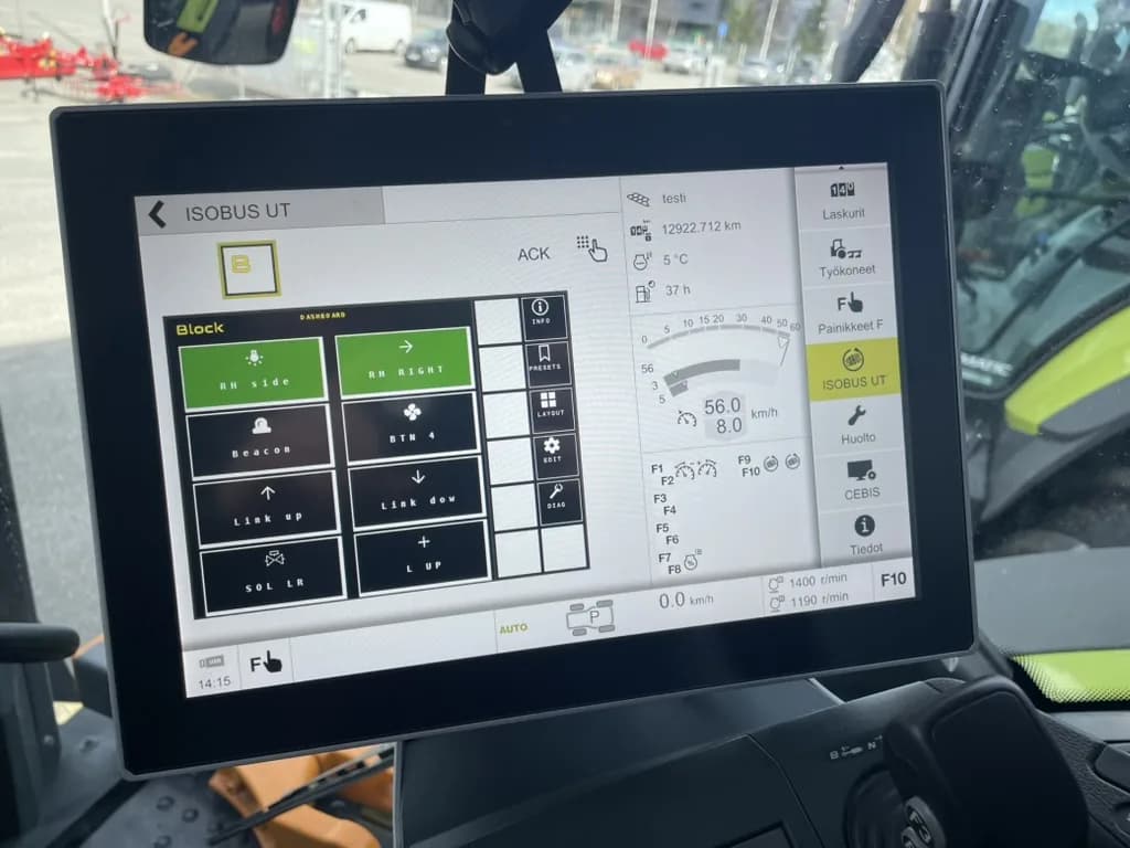
The Virtual Terminal interface shows the real-time status of all 8 relay outputs on ISOBUS Block. You can see immediately which channels are active and which are not responding. If a relay isn't switching when commanded, you see it on the VT. No need to walk out to the implement.
The optional WiFi diagnostic view on your phone or tablet shows the same 8 output states plus the installed firmware version and basic health checks. All button and channel configuration stays on the VT.
For more on diagnosing connection issues with your ISOBUS equipment, see our ISOBUS Troubleshooting Guide.
Frequently Asked Questions
What do ISOBUS fault codes mean?
ISOBUS fault codes are standardized diagnostic messages that identify problems on the CAN bus network. Each code consists of an SPN (Suspect Parameter Number) identifying the component and an FMI (Failure Mode Identifier) describing the type of failure. Together they tell you what went wrong and where.
How do I read ISOBUS fault codes on my tractor?
Fault codes appear on your tractor's Virtual Terminal display, either as automatic alarm screens or through the diagnostic menu. Navigate to your VT's ISOBUS diagnostics section to view active and stored fault codes. The exact menu location varies by tractor brand.
What is SPN and FMI in fault codes?
SPN (Suspect Parameter Number) identifies which component or parameter has a fault. For example, SPN 168 refers to battery voltage. FMI (Failure Mode Identifier) describes how it failed. For example, FMI 1 means the value is below normal range. Together, SPN 168 FMI 1 means "battery voltage critically low."
Can I clear ISOBUS fault codes myself?
Stored (inactive) fault codes can usually be cleared through your tractor's VT diagnostic menu after fixing the underlying problem. Active fault codes will clear automatically once the condition is resolved. Some codes may require manufacturer diagnostic tools to clear.
Why does my ISOBUS show a communication error?
Communication errors (typically SPN 639 or SPN 2000) usually indicate CAN bus wiring problems: loose connections, incorrect termination, damaged cables, or electromagnetic interference. Check all physical connections first, then verify CAN bus termination measures approximately 60 ohm between CAN_H and CAN_L.
What does FMI 9 mean?
FMI 9 means "abnormal update rate": the system expected to receive periodic messages from a device but they stopped arriving on time. The ECU has lost communication: disconnected cable, power loss, or a device malfunction.
Related Resources
- ISOBUS Troubleshooting Guide: Practical solutions for common connection problems
- ISOBUS Connector Pinout Guide: Pin functions and wiring details
Need relay control with real-time diagnostics? ISOBUS Block shows the status of all 8 relay outputs on your Virtual Terminal, so you can spot output issues without leaving the cab. For firmware update and output troubleshooting questions, the FAQ covers the most common ones. Learn more or contact us.