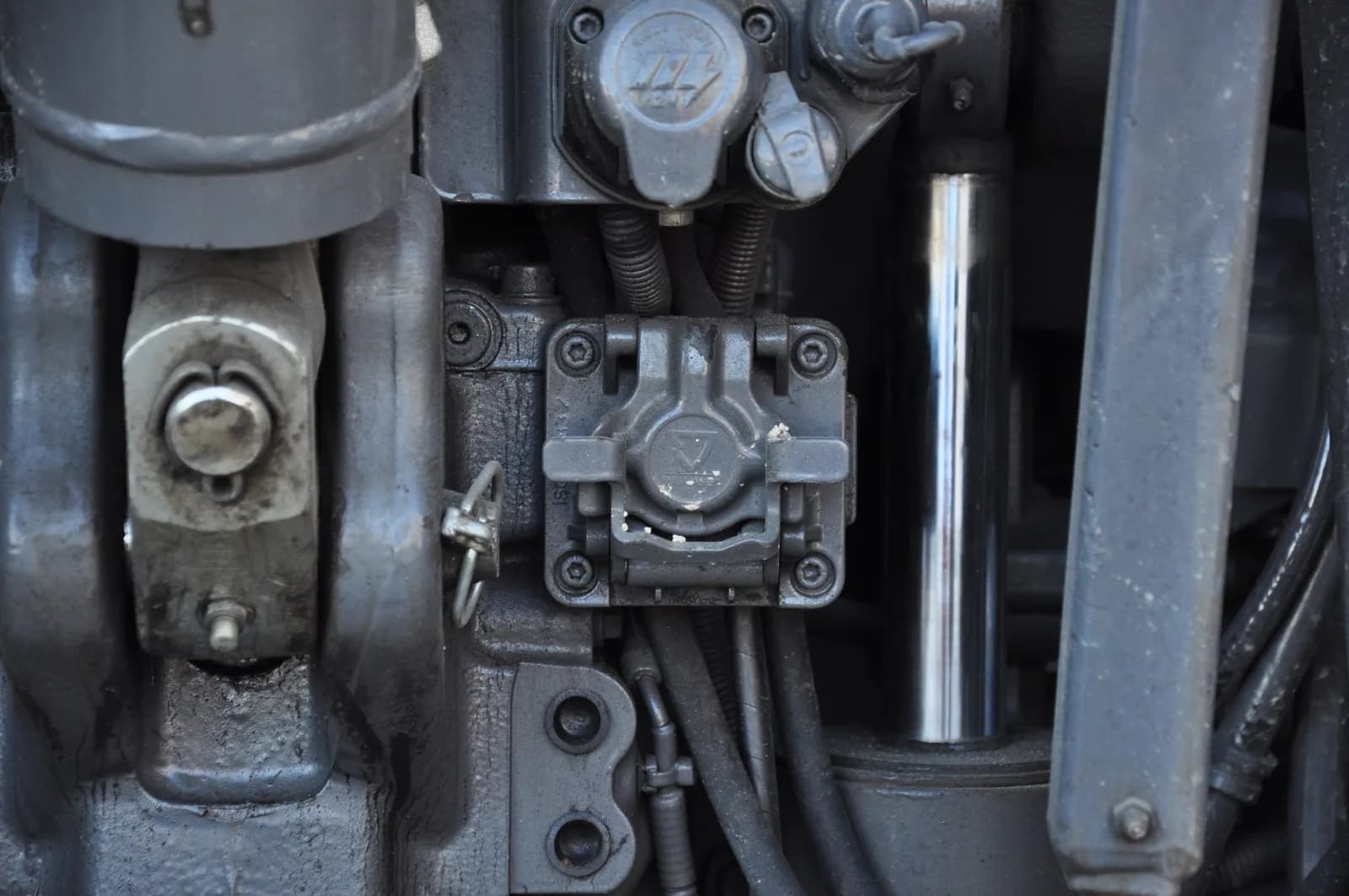
In short: Every ISOBUS tractor has two 9-pin sockets with different pin layouts, and they do not mate. The rear external connector carries one CAN bus: CAN_H on pin 8, CAN_L on pin 9, ECU power on pin 4. The in-cab connector carries two CAN buses, and ISOBUS Block uses four of its pins: CAN_L on 2, CAN_H on 4, BAT+ on 7 and ground on 9.
The ISOBUS connector is standardized under ISO 11783-2. There are two sockets on every ISOBUS tractor: the rear external connector (where implements plug in) and the in-cab connector (inside the cab, for displays, relay modules, and diagnostic tools). Both have 9 pins, but they are different connectors with different pin layouts. The rear plug is a large bayonet-locked shell, the in-cab plug a smaller circular one, and they do not mate with each other. Mix up the pin tables and nothing communicates. At the rear, the ISOBUS socket sits next to the 3-pin, 7-pin and signal sockets, which are separate connectors with their own jobs.
Here to buy a plug or cable rather than read pin tables? The ISOBUS plug and connector guide covers part numbers, cable and where to buy.
This page is the full pinout reference for both. Use it for wiring an aftermarket device, building a harness, or chasing a CAN bus fault.
Key Takeaways
- The rear external and in-cab connectors both have 9 pins, but they are different connectors with different pin assignments, and they do not mate.
- The rear external connector carries one CAN bus. The in-cab connector carries two: CAN 1 (tractor bus) and CAN 2 (outward to devices/implements).
- CAN bus runs at 250 kbit/s with 120 ohm termination at each physical end of the network.
- Power on the in-cab socket is on pin 7 (BAT+) and ground on pin 9 (GND). On the rear external socket, pin 1 is chassis ground and ECU power moves to pin 4.
- The connector is the same on every ISOBUS tractor brand. There is no brand-specific variant.
Rear External ISOBUS Connector Pinout
The rear external connector is the main link between tractor and implement. It sits at the rear of the tractor near the hydraulic couplers and is designed to release cleanly if the implement separates unexpectedly.
Pin Functions - Rear External
| Pin | Signal | Function |
|---|---|---|
| 1 | Ground | Chassis ground connection |
| 2 | ECU_GND | ECU signal ground |
| 3 | Power | Unswitched battery power |
| 4 | ECU_PWR | ECU power supply (12V/24V) |
| 5 | TBC_CONNECT | Factory bridged, do not wire |
| 6 | TBC_PWR | TBC power output |
| 7 | TBC_RET | TBC return path |
| 8 | CAN_H | CAN bus high |
| 9 | CAN_L | CAN bus low |
Active vs Passive
The rear external connector is a two-part design:
- Active (Master): black contact insert, on the tractor
- Passive (Slave): grey contact insert, on the implement
The active side supplies power and CAN signals. The passive side receives them. If you're building a custom implement harness, you need the passive (grey) connector on the implement end. The rear external ISOBUS connector is also designed to release cleanly if the implement separates from the tractor unexpectedly: the contacts disengage without damaging the wiring or exposing live pins. For the full overview of connector types, suppliers, and specs, see the ISOBUS Connector Buying Guide.
In-Cab ISOBUS Connector Pinout
The in-cab connector lives inside the tractor cab, usually on the right side of the operator's seat or on the B-pillar. It's the connection point for aftermarket Virtual Terminals, relay modules, diagnostic tools, and precision-ag controllers that need to talk to the ISOBUS network without being attached to a rear implement.
Pin Functions - In-Cab
| Pin | Signal | Function |
|---|---|---|
| 2 | CAN_L | CAN low |
| 4 | CAN_H | CAN high |
| 7 | BAT+ | Power supply (12V or 24V) |
| 9 | GND | Ground |
These are the four pins ISOBUS Block connects to on the in-cab socket. The connector's other pins carry the tractor's internal CAN bus, cable shield, and grounds, and are not used by the module.
Two CAN Buses: What They Mean
This is the key difference from the rear external connector. The in-cab socket carries two separate CAN buses.
CAN 1 is the input side, on pin 2 (CAN_L) and pin 4 (CAN_H). It connects directly to the tractor's internal ISOBUS network, the same bus the Virtual Terminal, instrument cluster, and tractor ECUs sit on. A device wired here sees the full tractor network.
CAN 2 is the output side. It routes outward to external devices or downstream implements. The in-cab socket can act as an ISOBUS gateway: data from CAN 1 is forwarded onto CAN 2 for whatever is connected here.
Most aftermarket devices (relay modules, additional displays, diagnostic tools) connect to CAN 1. That's where the Virtual Terminal and tractor ECUs live. CAN 2 exists for daisy-chaining or for routing data to implements, but most cab-mounted devices only need CAN 1.
Where to Find the In-Cab Socket
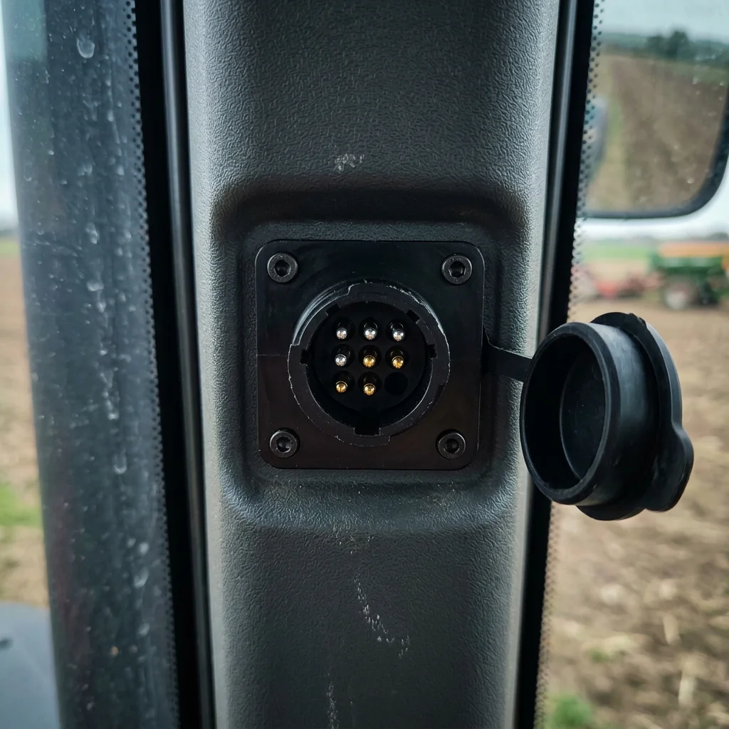
The location is standardized under ISO 11783-2: right side of the operator's seat, near the armrest or B-pillar. On most modern tractors it's a female 9-pin socket with a protective dust cap.
Not every tractor ships with it populated. Some brands fit the socket as standard; others fit it as an option. If your tractor has an ISOBUS-capable Virtual Terminal but no cab socket visible, check the manual. The socket may be present but unpopulated, or available as a dealer-fit option.
In-Cab vs Rear External - Side by Side
The two sockets are not interchangeable. Mixing them up is the most common wiring fault on aftermarket installs: the device powers up but never appears on the Virtual Terminal.
| In-cab connector | Rear external connector | |
|---|---|---|
| CAN buses | 2 (input + output) | 1 |
| Location | Inside cab | Rear of tractor |
| Typical use | Displays, controllers, diagnostics | Implement communication |
If your device powers up but won't communicate, check which connector type you wired into first.
CAN Bus Signals and Termination
The ISOBUS network runs CAN (Controller Area Network) on top of the physical layer above.
- CAN_H (Pin 8 on rear, Pin 4 on in-cab CAN 1): high signal line
- CAN_L (Pin 9 on rear, Pin 2 on in-cab CAN 1): low signal line
- Bit rate: 250 kbit/s, fixed for ISOBUS
Termination
The CAN bus needs 120 ohm termination at each physical end of the network. Typically:
- One terminator in the tractor
- One terminator in the last implement
If you're adding a device to an existing ISOBUS network, you usually don't add termination. Only enable it if your device is at the physical end of the bus. With the system powered off, measure between CAN_H and CAN_L. You should see roughly 60 ohm (two 120 ohm terminators in parallel).
Power Distribution
The rear external connector exposes several power options:
ECU Power (Pin 4, rear)
- Supplies power to implement ECUs
- Typically 12 V or 24 V depending on tractor
- Current limited by the tractor
TBC Power (Pin 6, rear)
- Terminating bias circuit power output, with its return on pin 7
- Powers the active terminator at the implement end of the bus
- Active connectors supply TBC_PWR by internal connection to ECU_PWR
- What the terminator does and how to test it: ISOBUS terminator (TBC) explained
On the in-cab connector, power is on pin 7 (BAT+) and ground on pin 9 (GND). The in-cab socket carries TBC power on pin 6 and TBC ground on pin 8, but the module does not use them.
Wiring Best Practices
Use Twisted Pair for CAN
Always run twisted pair for CAN_H and CAN_L. It reduces EMI and keeps the bus stable near hydraulic pumps and ignition systems.
Shielding
In electrically noisy installs, use shielded cable with the shield connected to chassis ground at one end only. Grounding both ends creates a ground loop and makes things worse.
Wire Gauge
| Application | Recommended Gauge |
|---|---|
| CAN signals | 0.5 - 1.0 mm2 |
| ECU power | 1.5 mm2 minimum |
| High-current loads | Size for actual current |
Connector Quality
Use proper ISOBUS-rated connectors. They're built for:
- A wide temperature range (the Amphenol rear plug is rated -40 C to +125 C)
- Vibration and mechanical stress
- IP67 ingress protection or better
What Connects to the In-Cab Socket
Any ISOBUS device mounted inside the cab connects here:
- Aftermarket Virtual Terminals: additional screens when the tractor's built-in display is too small or not ISOBUS-capable
- Relay modules: like ISOBUS Block, which adds 8 relay outputs you control from the tractor's existing screen and joystick buttons
- Diagnostic tools: service laptops and handheld diagnostics that need access to the full tractor bus
- Data logging devices: field computers and precision agriculture controllers that read live tractor data
The in-cab connector gives all of these devices the same network access as built-in tractor ECUs. That's why it's the preferred connection point for cab-mounted ISOBUS equipment, and why any ISOBUS retrofit that adds a display or aftermarket controller lands on this same 9-pin socket.
Connecting ISOBUS Block
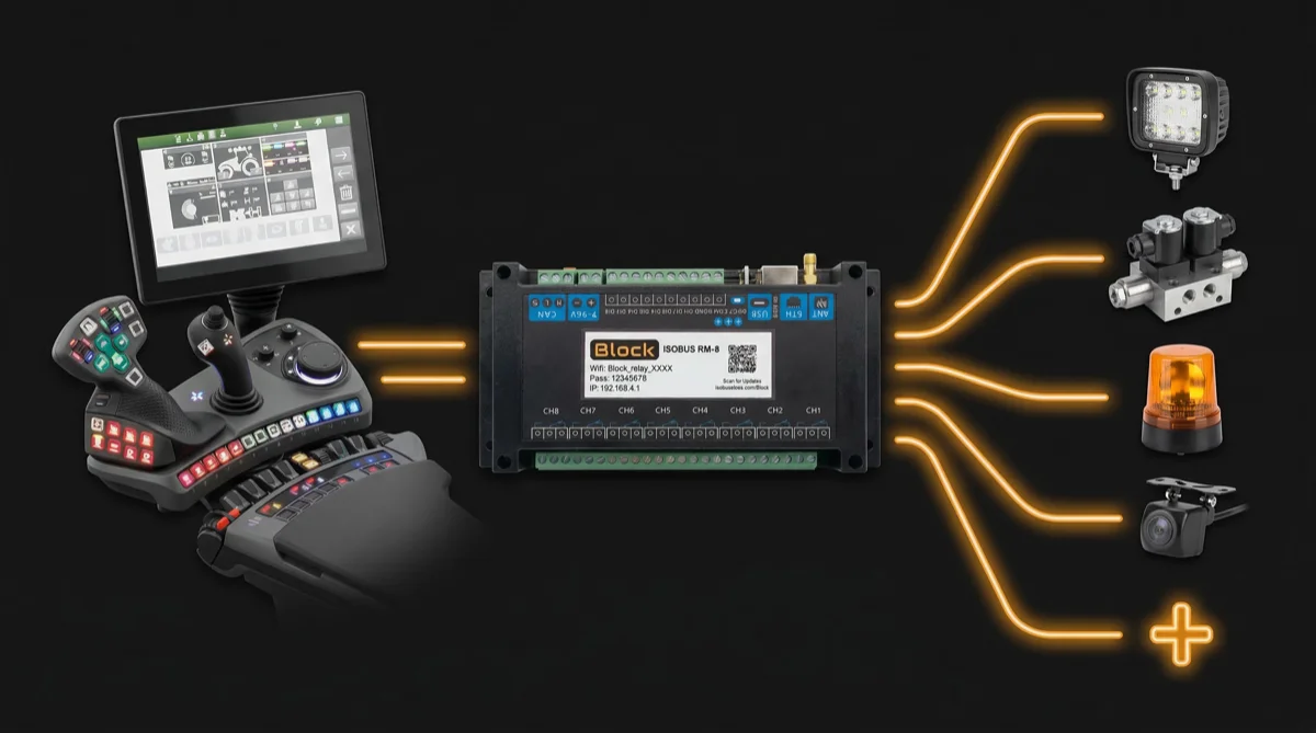
ISOBUS Block is an 8-channel relay module that connects through the standard 9-pin connector, either the in-cab socket or the rear external socket. It communicates on CAN 1 (the tractor's internal bus), so it shows up on the Virtual Terminal automatically. No extra display required.
The module draws its CAN signal and supply power through the ISOBUS connection itself. There is no separate power harness. The relay side stays open: each channel switches the circuit you wire to its NO/COM/NC terminals, so the load's power, ground, and current draw are whatever you connect.
From the Virtual Terminal you assign each relay output to a joystick button or screen control. Wire a work light to channel 1, a diverter valve to channel 2, assign them to armrest buttons. Done. The tractor remembers your assignments. For the AUX-N button-binding workflow, see ISOBUS AUX-N: Complete Guide.
Common Issues
No Communication
- Check CAN_H and CAN_L connections
- Verify termination (~60 ohm between CAN_H and CAN_L with bus powered off)
- Look for reversed CAN_H/CAN_L wires
- Confirm you're on the right socket: in-cab vs rear external use different pin assignments
Intermittent Connection
- Check connector seating and the bayonet collar
- Look for corroded pins
- Verify wire crimps are secure
- Check for damaged cables and chafe points
Device Not Appearing on Virtual Terminal
- Wait 30 seconds after power-on. VT object pool upload takes time.
- Verify supply voltage at the connector
- Check CAN bus connectivity end-to-end
- Ensure device firmware supports ISOBUS VT
For deeper diagnostics, the ISOBUS Troubleshooting Guide covers the common faults in detail.
ISOBUS connector by tractor brand
| Brand | Rear connector | In-cab connector |
|---|---|---|
| John Deere | ISO 11783-2, 9-pin | ISO 11783-2, 9-pin |
| Fendt | ISO 11783-2, 9-pin | ISO 11783-2, 9-pin |
| Case IH | ISO 11783-2, 9-pin | ISO 11783-2, 9-pin |
| New Holland | ISO 11783-2, 9-pin | ISO 11783-2, 9-pin |
| CLAAS | ISO 11783-2, 9-pin | ISO 11783-2, 9-pin |
| Valtra | ISO 11783-2, 9-pin | ISO 11783-2, 9-pin |
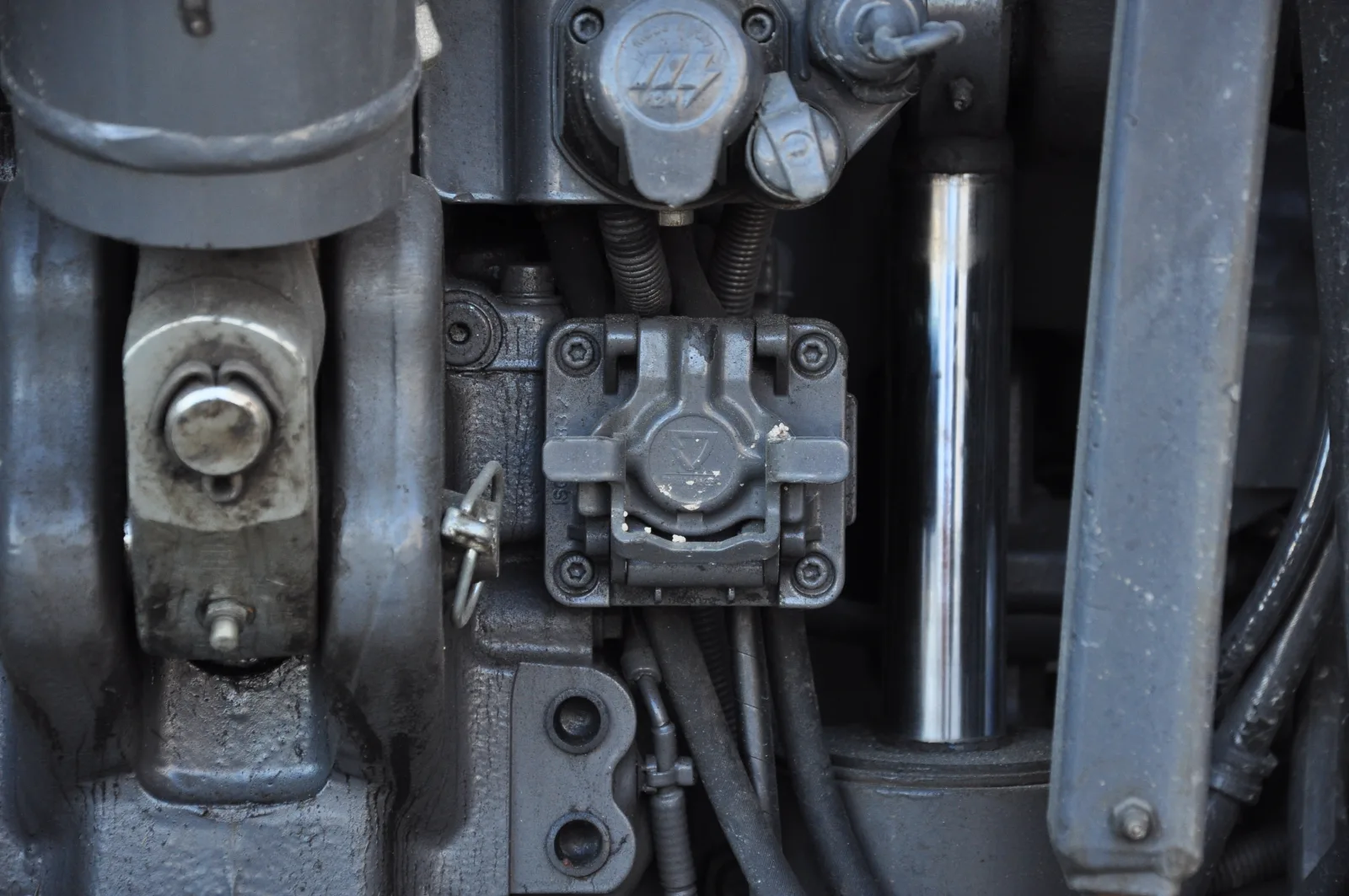
Every ISOBUS tractor uses the same two connectors and the same pinouts above, so a harness wired for one brand plugs into the others.
Frequently Asked Questions
What are the ISOBUS connector pin numbers?
Both ISOBUS connectors have 9 pins. On the rear external connector, pin 1 is chassis ground, pins 2-4 handle ECU ground and power, pins 5-7 are for the terminating bias circuit (TBC), and pins 8-9 are CAN_H and CAN_L. On the in-cab connector, ISOBUS Block uses four pins: pin 2 is CAN_L, pin 4 is CAN_H, pin 7 is BAT+ (power), and pin 9 is GND. The connector's other pins carry the tractor's internal CAN bus and grounds and are not used by the module. Same pin count, different connector and layout.
What is the difference between the in-cab and rear external connector?
Both are 9-pin connectors defined by ISO 11783-2, but they are different parts, and the pin assignments and number of CAN buses differ. The rear external connector carries one CAN bus and uses pin 1 as chassis ground. The in-cab connector carries two CAN buses (CAN 1 = tractor internal, CAN 2 = outward) and supplies power on pin 7 (BAT+) with ground on pin 9. They are not interchangeable.
Do I need a termination resistor for ISOBUS?
The ISOBUS CAN bus needs exactly two 120 ohm termination resistors, one at each physical end of the network. Most tractors have the tractor-side terminator built in. If you're adding a device mid-bus, you typically don't add termination. Measure between CAN_H and CAN_L with the system off. You should read roughly 60 ohm.
What voltage does ISOBUS use?
ISOBUS systems run at either 12 V or 24 V depending on the tractor's electrical system. On the rear connector this is the ECU_PWR pin (pin 4); on the in-cab connector the module takes power from pin 7 (BAT+). CAN bus signalling itself uses differential signalling at around 2.5 V.
What is the ISOBUS connector called?
Two customer-facing names: the rear external ISOBUS connector (back of the tractor, where implements plug in) and the in-cab ISOBUS connector (inside the cab, for displays and aftermarket controllers). A front external ISOBUS connector is optional on some tractors and uses the same plug as the rear one. All three have 9 pins, but the in-cab plug is a different, smaller connector.
Is ISOBUS the same as CAN bus?
ISOBUS is built on CAN bus. It adds agricultural-specific protocols on top. ISOBUS uses ISO 11783, derived from SAE J1939. The physical layer (connectors, wiring) and data rate (250 kbit/s) are standardized for agricultural equipment.
What wire gauge should I use for ISOBUS?
For CAN signal wires (CAN_H and CAN_L), use 0.5 - 1.0 mm2 twisted pair. For power conductors, use at least 1.5 mm2, sized for the actual current draw of the connected equipment.
Related Resources
- ISOBUS Connector Buying Guide: Connector types, suppliers, and what to buy
- ISOBUS Troubleshooting Guide: Solve common connection faults
- ISOBUS AUX-N: Complete Guide: Assign relay channels to joystick buttons
Need an ISOBUS relay module for controlling solenoids, work lights, or hydraulic valves? ISOBUS Block gives you 8 relay outputs controlled from your tractor's Virtual Terminal display. Wiring and installation questions (separate power supply, termination, which socket to use) are answered on the FAQ page. See how it works.