In short: Most ISOBUS connection problems come down to power, a connector not fully seated, CAN bus termination or a corrupted object pool. With the tractor off, measure between CAN_H and CAN_L at the socket: about 60 ohms is correct, and 120 ohms means one terminator is missing. If the implement still does not appear, clear the stored object pools on the VT and restart.
ISOBUS is plug-and-play most of the time. When it isn't, connection problems usually come down to a short list of causes. Here's how to run ISOBUS troubleshooting step by step, from quick checks to CAN bus diagnostics and fault code lookup.
ISOBUS Troubleshooting: Quick Diagnostics Checklist
Before diving into specific issues, check these basics:
- Power - Is the implement getting proper voltage (12V or 24V)?
- Connections - Are all ISOBUS connectors fully seated?
- Wait time - Have you waited 30-60 seconds after connecting?
- VT status - Does the Virtual Terminal show any error indicators?
CAN Bus Termination Issues
Termination problems are one of the most common causes of ISOBUS communication failures. The CAN bus requires exactly two 120Ω termination resistors - one at each end of the network. The ISOBUS terminator (TBC) guide shows where each one sits and when you need to add one.
How Termination Works
When properly terminated, measuring resistance between CAN_H and CAN_L (with the system powered off) should show approximately 60Ω. This is because two 120Ω resistors in parallel equal 60Ω.
| Measurement | Meaning |
|---|---|
| ~60Ω | Correct - two terminators present |
| ~120Ω | One terminator missing |
| Very high/infinite | No termination - major problem |
| Lower than 60Ω | Too many terminators or short circuit |
How to Measure
- Turn off the tractor (main switch off)
- Disconnect the implement
- Set multimeter to resistance (Ω) mode
- Measure between CAN_H (pin 8) and CAN_L (pin 9) at the tractor's ISOBUS socket
- Note the reading
Tractor-Side Termination
Many tractors have a removable termination resistor - typically a small 2-pin Deutsch connector that looks like a plug. It's often located:
- Under plastic covers near the rear ISOBUS socket
- Inside the cab near the diagnostic port
- Behind panels in the A-pillar area
Try removing the tractor's termination plug if you're having communication issues, especially if you've added multiple ISOBUS devices. Then measure again - you should see ~120Ω if only the implement's terminator remains.
Automatic Termination Relays
Some modern tractors have automatic CAN bus termination - a relay that connects or disconnects the 120Ω resistor based on detected bus conditions. If this relay or its control circuit fails, you'll have termination problems.
Symptoms of a faulty termination relay:
- Intermittent ISOBUS communication
- Works sometimes, fails other times
- Different behavior with different implements
Workaround: If you suspect the automatic termination is faulty, try manually adding a 120Ω resistor between CAN_H and CAN_L at the ISOBUS socket, then restart the entire system.
Adding Manual Termination
If termination is missing, you can add it yourself:
- Get a 120Ω 1/4W resistor (or purpose-made CAN terminator)
- Connect it between CAN_H and CAN_L
- Restart the tractor and implement
- Check if communication is restored
Virtual Terminal Object Pool Issues
The Virtual Terminal stores "object pools" - the screen layouts and graphics uploaded by each implement. Corrupted or conflicting pools can cause display problems or prevent implements from appearing.
Symptoms of Pool Problems
- Implement connected but nothing appears on VT
- Garbled or corrupted graphics
- VT shows old/wrong implement screens
- "Pool loading" gets stuck or fails
How to Clear Object Pools
Most Virtual Terminals have a settings or diagnostics page where you can manage loaded pools:
- Disconnect all ISOBUS implements
- Navigate to VT settings/diagnostics menu
- Find "Object Pools", "Loaded Pools", or similar
- Delete all stored pools
- Turn off tractor with main switch (full power cycle, not just ignition)
- Wait 30 seconds
- Turn tractor back on
- Reconnect the implement
The implement will upload its pool as if connecting for the first time.
Pool Management by Brand
| Brand | Where to Find Pool Settings |
|---|---|
| John Deere | Generation 4 and G5 displays: ISOBUS VT app settings → advanced settings → Clean Up ISOBUS VT (John Deere guide) |
| Fendt | Variotronic terminal → Settings → ISOBUS configuration |
| Case IH / New Holland | AFS display → Settings → ISOBUS → Object pools |
| Massey Ferguson | Datatronic terminal → Setup → ISOBUS settings |
| Claas | CEBIS terminal → Settings → ISOBUS → Pool management |
| Valtra | SmartTouch display → Settings → ISOBUS |
| Deutz-Fahr | iMonitor → System settings → ISOBUS |
| Kubota | K-Monitor → Settings → ISOBUS configuration |
| AGCO (Challenger, etc.) | C1000 terminal → Setup → ISOBUS pools |
| JCB | LiveLink display → Settings → ISOBUS |
| McCormick | Digital terminal → ISOBUS settings |
Menu names may vary by model year and software version. Consult your operator's manual for exact navigation.
Implement Not Appearing on VT
If your implement doesn't show up on the Virtual Terminal, the short in-cab version is the ISOBUS not working checklist. The full steps:
Step 1: Verify Physical Connection
- Check the ISOBUS cable for damage
- Ensure connectors are fully seated (you should hear/feel a click)
- Try a different ISOBUS socket if available (front vs rear)
If you're unsure which connector type you're working with (rear external, in-cab, or front external), the ISOBUS Plug & Connector Guide explains the differences and what to look for when sourcing replacements. Freshly wired retrofit installations are especially prone to miscrimped pins and reversed CAN_H/CAN_L. Inspect the crimping on the first suspicious fault.
Step 2: Check Power
- Verify implement is receiving power
- Some implements have separate power requirements beyond ISOBUS
- Check fuses on both tractor and implement
Step 3: Wait and Restart
ISOBUS devices go through a startup sequence:
- Power on
- Address claiming (devices negotiate unique addresses)
- VT client connection
- Object pool upload
Wait at least 60 seconds before assuming there's a problem. If still nothing:
- Turn off implement
- Turn off tractor (main switch)
- Wait 30 seconds
- Turn on tractor, wait for VT to fully boot
- Turn on/connect implement
Step 4: Check for Address Conflicts
Each ISOBUS device needs a unique address. Conflicts can prevent devices from communicating. If you have multiple implements or aftermarket controllers, try:
- Connecting only one device at a time
- Checking each device's documentation for address configuration
- Looking for "address claim" errors in VT diagnostics
Intermittent Communication
Random disconnections or erratic behavior often indicate:
Wiring Problems
- Loose connections that vibrate apart
- Damaged cables (check for cuts, crushing, corrosion)
- Poor crimps or cold solder joints
- Water ingress in connectors
Electrical Noise
Agricultural equipment generates significant electrical noise. If problems occur when:
- Hydraulics are operating
- Engine RPM changes
- Certain implements are active
Try:
- Routing ISOBUS cables away from hydraulic pumps and solenoid valves
- Using shielded cable for long runs
- Ensuring good chassis ground connections
Power Supply Issues
Voltage drops or spikes can disrupt CAN communication:
- Check battery condition
- Check alternator output
- Look for loose battery terminals or ground straps
Using Diagnostic Tools
Built-in VT Diagnostics
Most Virtual Terminals have diagnostic screens showing:
- Connected devices and their addresses
- CAN bus status and error counts
- Loaded object pools
Access these through the VT's settings or service menu.
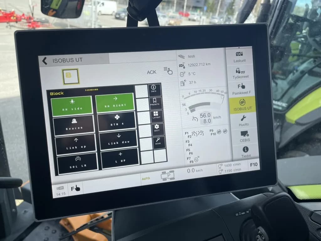
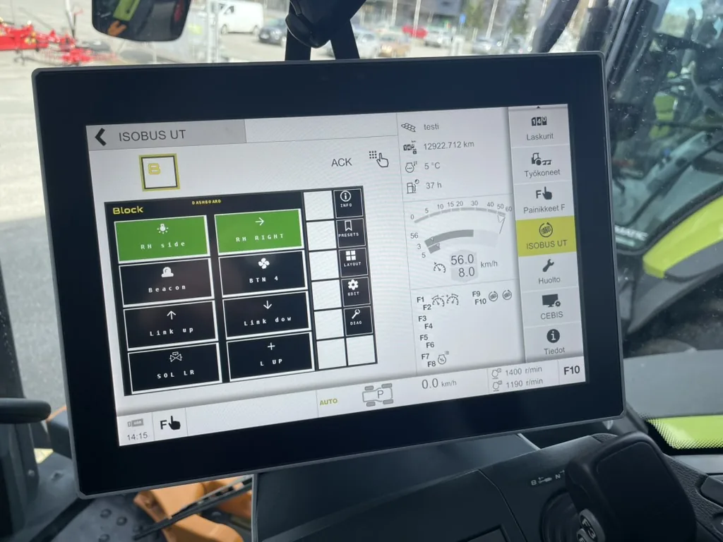
For relay-based setups, ISOBUS Block adds a second diagnostic layer: the Virtual Terminal shows real-time status of all 8 relay outputs, and the optional WiFi diagnostic view shows the same output states plus firmware version from your phone. Useful in the field when you need to isolate whether a problem is on the CAN bus side or the load side. (Button and channel configuration stays on the VT.)
Multimeter Checks
| Test | Expected Value |
|---|---|
| CAN_H to CAN_L resistance (system off) | ~60Ω |
| ECU_PWR voltage (system on) | 12V or 24V (±10%) |
| CAN_H to ground voltage (system on, idle) | ~2.5V |
| CAN_L to ground voltage (system on, idle) | ~2.5V |
Professional Diagnostics
For persistent problems, consider:
- Dealer diagnostic tools (specific to tractor brand)
- Generic CAN bus analyzers
- ISOBUS-specific diagnostic software
ISOBUS Fault Codes: What They Mean
When a device on the ISOBUS network detects a problem, it broadcasts a fault code over the CAN bus. These diagnostic trouble codes (DTCs) appear on your tractor's Virtual Terminal, either as an automatic alarm screen or in the VT's diagnostics menu.
Every ISOBUS fault code has two parts:
- SPN (Suspect Parameter Number): identifies what has the problem (e.g., battery voltage, CAN bus data link)
- FMI (Failure Mode Identifier): identifies how it failed (e.g., voltage too low, communication lost)
The combination tells you both where the fault is and what kind of failure occurred. For example, SPN 168 FMI 1 translates to "battery voltage is critically low."
Common Fault Codes at a Glance
| Code | Meaning | First Check |
|---|---|---|
| SPN 639 FMI 2 | CAN bus data erratic | Termination resistance (should be ~60Ω) |
| SPN 639 FMI 19 | CAN messages received in error | Check for swapped CAN_H/CAN_L wires |
| SPN 2000 FMI 9 | ECU not communicating (missed messages) | Physical connection and power to ECU |
| SPN 2000 FMI 12 | ECU internal fault | Power cycle; may need dealer service |
| SPN 168 FMI 0 | Battery voltage too high (>16V on 12V systems, >32V on 24V systems) | Check alternator output |
| SPN 168 FMI 1 | Battery voltage too low (<9V on 12V systems) | Check battery, terminals, alternator |
| SPN 3480 FMI 31 | Virtual Terminal status condition | Clear VT object pools, power cycle |
| SPN xxxx FMI 3 | Sensor voltage too high | Check sensor connector and wiring |
| SPN xxxx FMI 4 | Sensor voltage too low (short to ground) | Inspect for chafed wiring, water ingress |
How to Access Fault Codes on Your VT
Fault codes appear automatically as alarm screens when they occur. You can also review stored faults through the VT diagnostics menu:
| Brand | Navigation |
|---|---|
| John Deere | Generation 4 and G5 displays: controller status in Status Center, details in Diagnostic Center. Older GreenStar displays: the diagnostics menu (John Deere guide) |
| Fendt | Variotronic → Settings → Diagnostics → ISOBUS fault memory |
| Case IH / New Holland | AFS display → Diagnostics → ISOBUS → Fault codes |
| Massey Ferguson | Datatronic → Service → ISOBUS diagnostics |
| Claas | CEBIS → Diagnostics → ISOBUS → Error memory |
| Deutz-Fahr | iMonitor → Service → ISOBUS diagnostics |
After fixing the underlying problem, stored (inactive) fault codes can usually be cleared through the same diagnostics menu. Active codes clear automatically once the condition is resolved.
For a full explanation of SPN/FMI numbers, all failure mode types, and systematic troubleshooting steps by fault category, see our ISOBUS Fault Codes Guide.
How to Check ISOBUS Compatibility
Before connecting an implement or relay module, it helps to confirm that your tractor and the new device will actually work together. ISOBUS (ISO 11783) is designed for universal compatibility, but specific features depend on what both sides support.
The Four Layers of Compatibility
- Physical: The 9-pin ISOBUS connector fits and delivers power and CAN signals
- Communication: Both devices run at 250 kbit/s on the CAN bus
- Display: The tractor's Virtual Terminal can render the implement's interface
- Features: Advanced capabilities like AUX-N or Task Controller require support on both sides
Most basic connection issues appear at layer 2 (CAN bus wiring/termination). Most feature problems appear at layer 4.
Practical Compatibility Checklist
1. Confirm your tractor has ISOBUS Look for a 9-pin circular connector at the rear, usually near the hydraulic couplers. Check your operator's manual for ISOBUS or ISO 11783 in the specifications.
2. Check VT version Navigate to the VT's settings or information screen. It will display the VT version number. VT 4 (common on 2010-2018 tractors) handles the vast majority of implement interfaces. VT 6 is the current standard.
3. Verify AUX-N if you need button control Look for an "Auxiliary functions" or "AUX-N assignment" menu in your VT settings. If it's not there, your tractor may only support AUX-O (older, less flexible) or no auxiliary input. Without AUX-N, you control the implement using on-screen soft keys. It is still fully functional, just less convenient.
4. Check the compatibility lists Check the terminal maker's compatibility list and the implement maker's spec sheet. Look up your tractor and implement to see their supported ISOBUS functionalities side by side.
5. Test before committing If possible, connect the implement and verify communication before completing an installation. Many compatibility issues appear immediately: implement not showing on VT, AUX-N functions missing, graphics problems.
Common Compatibility Problems and Fixes
| Problem | Likely Cause | Fix |
|---|---|---|
| Implement not appearing on VT | ISOBUS not activated on tractor | Contact dealer to enable ISOBUS |
| AUX-N functions missing | Tractor doesn't support AUX-N | Use VT soft keys; check the compatibility list |
| Works on one tractor, not another | Different ISOBUS feature levels | Compare tractor specs; check CAN bus health on failing unit |
| Graphics look wrong | VT version mismatch | Functional issue only; contact implement manufacturer for updated pool |
To check whether a tractor has ISOBUS at all, which terminal it carries, and where compatibility problems come from, see the ISOBUS tractor guide.
When to Seek Help
Contact your dealer or the implement manufacturer if:
- You've tried all troubleshooting steps without success
- There's physical damage to connectors or cables
- The problem started after a firmware update
- Multiple implements have the same issue on your tractor
Frequently Asked Questions
What do ISOBUS fault codes mean and how do I read them?
ISOBUS fault codes are standardized diagnostic messages broadcast over the CAN bus. Each code has two parts: an SPN (Suspect Parameter Number) that identifies the component with the problem, and an FMI (Failure Mode Identifier) that describes how it failed. For example, SPN 168 FMI 1 means "battery voltage is critically low." Codes appear on your Virtual Terminal as alarm screens or through the VT's diagnostics menu. See our ISOBUS Fault Codes Guide for a complete reference.
How do I check if my tractor and implement are ISOBUS compatible?
Start by confirming both devices are ISOBUS (ISO 11783) certified: look for the 9-pin connector on the tractor and check the terminal maker's compatibility list and the implement maker's spec sheet. Basic plug-and-play compatibility is standard, but specific features like AUX-N joystick control or Task Controller require both tractor and implement to support the same functionality. Check your tractor's VT settings for its version number, and verify AUX-N support in the auxiliary functions menu. Our ISOBUS Compatibility Guide covers this step by step.
Why is my ISOBUS implement not showing on the Virtual Terminal?
The most common causes are: incorrect CAN bus wiring (check CAN_H and CAN_L connections), missing or incorrect termination (should measure 60Ω between CAN_H and CAN_L), insufficient wait time (allow 60 seconds after connecting), or corrupted object pools in the VT. Try clearing all pools from the VT and restarting the system.
How do I know if my ISOBUS termination is correct?
With the system powered off, measure resistance between CAN_H (pin 8) and CAN_L (pin 9). A reading of approximately 60Ω indicates correct termination (two 120Ω resistors in parallel). If you read 120Ω, one terminator is missing. Very high resistance means no termination is present.
What does it mean when ISOBUS keeps disconnecting?
Intermittent disconnections usually indicate loose connections, damaged cables, or electrical noise interference. Check all connectors are fully seated, inspect cables for damage, and try routing ISOBUS wiring away from hydraulic pumps and solenoid valves which generate electrical noise.
How do I reset the ISOBUS Virtual Terminal?
Disconnect all ISOBUS implements. Delete all stored object pools from the VT settings menu. Turn off the tractor using the main switch, not just the ignition. Wait 30 seconds, restart, then reconnect your implement. The implement uploads its pool as if connecting for the first time.
Can I add a 120 ohm resistor myself to fix ISOBUS?
Yes, if termination is missing or faulty, you can add a 120Ω resistor between CAN_H and CAN_L. Use a 1/4W resistor or a purpose-made CAN terminator. This is a valid workaround if your tractor's automatic termination relay has failed.
Why does my ISOBUS work on some tractors but not others?
Different tractors handle termination differently - some have automatic termination relays, others have removable termination plugs, and some have fixed termination. The total termination resistance must equal 60Ω for reliable communication. Also check that both tractors have compatible ISOBUS versions.
How long should I wait for an ISOBUS device to connect?
Wait at least 60 seconds after connecting power. ISOBUS devices go through a startup sequence: power-on, address claiming, VT client connection, and object pool upload. Complex implements with large graphics may take longer to upload their pool.
What is an ISOBUS object pool?
An object pool is the collection of screen layouts, buttons, and graphics that an implement uploads to the Virtual Terminal. The VT stores these pools so they don't need to be uploaded every time. Corrupted pools can cause display problems and may need to be deleted.
How do I find the ISOBUS termination resistor on my tractor?
Look for a small 2-pin Deutsch connector that looks like a plug, usually located under plastic covers near the rear ISOBUS socket, inside the cab near the diagnostic port, or behind A-pillar panels. This removable plug contains the 120Ω termination resistor.
Related Resources
- ISOBUS Fault Codes Guide: Complete SPN/FMI reference with troubleshooting steps by fault category
- ISOBUS Compatibility Guide: VT versions, AUX-N support, and brand-specific compatibility notes
- ISOBUS Connector Pinout Guide: Pin functions and wiring details
Having trouble with your ISOBUS equipment? ISOBUS Block shows real-time relay status on the Virtual Terminal and includes an optional WiFi diagnostic view (output states and firmware version). Check the ISOBUS Block troubleshooting guide for product-specific help, or browse the FAQ for quick answers to common setup and connection questions.