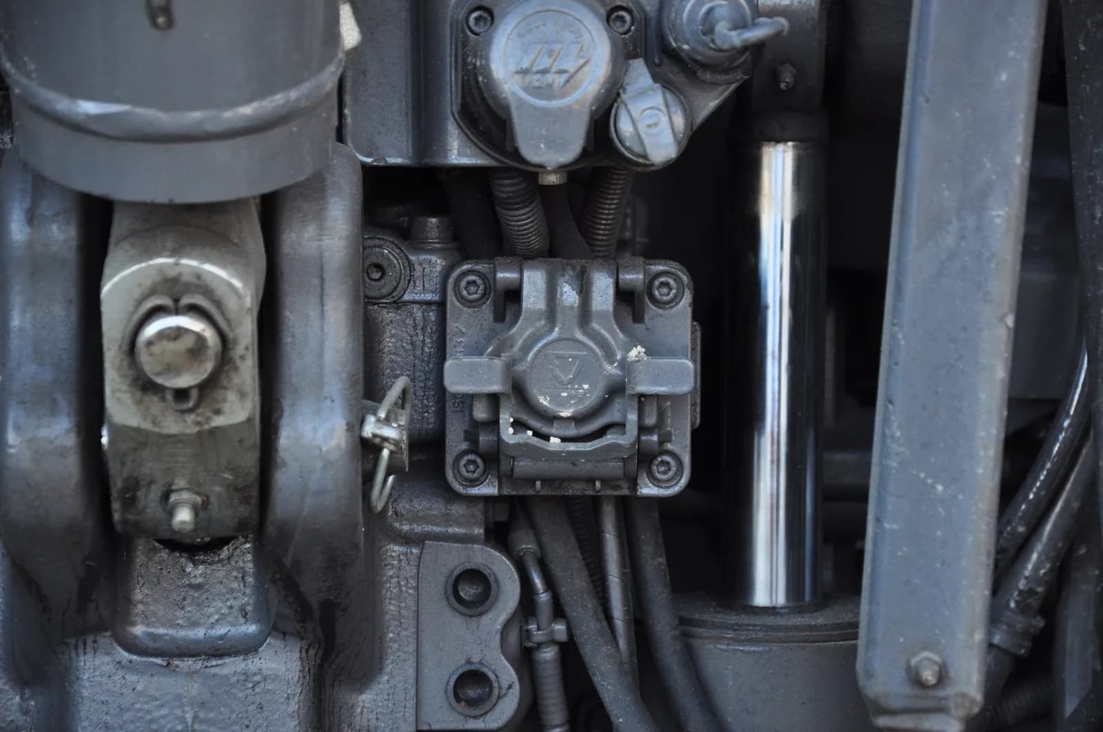
John Deere ISOBUS works like ISOBUS on any other brand: a 9-pin socket at the back, a 9-pin socket in the cab, and a display that shows the implement's screens. What differs is where Deere puts things and what the menus are called. Everything below comes from Deere's own operator manuals and display help pages. Model years and software differ, so when your manual disagrees with this page, your manual wins.
Where the ISOBUS sockets are on a John Deere
Deere's manuals for the 7R, 8R and 9R series call these tractors "ISOBUS ready" and list the same connections:
| Socket | Where Deere puts it | What it is |
|---|---|---|
| Implement connector, rear | Back of the tractor, with a release lever | The rear external ISOBUS connector. The implement plugs in here. |
| Implement connector, front | Front of the tractor, if equipped | Same connector, for a front-mounted ISOBUS implement |
| ISO 11783 connector | Right-hand console in the cab | The in-cab ISOBUS connector |
| ISO 11786 connector | Right corner post | Speed signal from radar or GPS. Not ISOBUS. |
| GreenStar connector | Left corner post | Deere's own display connection. Not ISOBUS. |
Lift the release before you pull the implement harness off the rear connector. Deere also warns that the in-cab socket is for ISO 11783 components only: anything else can damage the tractor's electronics. The 6R manual adds that the socket's supply circuit must never be overloaded, counting everything drawing current at once, across all sockets.
If the corner post has more round sockets than you expected, the tractor sockets guide shows which plug is which.
The John Deere ISOBUS connector is the standard 9-pin plug
Deere's manuals call the in-cab socket the "ISO 11783 standard connector" and the rear one a standardized connector that any ISO-compliant implement fits. There is no Deere-specific pinout, so a John Deere ISO plug diagram is the ISO 11783-2 one. The short version:
| Rear external connector | In-cab connector | |
|---|---|---|
| CAN high | Pin 8 | Pin 4 |
| CAN low | Pin 9 | Pin 2 |
| ECU power | Pin 4 | Pin 7 |
| ECU ground | Pin 2 | Pin 9 |
The full layout for both sockets, with the heavy supply pins and terminator pins, is in the ISOBUS connector pinout guide.
Termination. Deere's GreenStar 3 2630 manual gives the same bus check as everyone else: each terminator is about 120 ohms, so a working bus measures about 60 ohms between CAN high and CAN low. For where the terminators sit and when a front socket needs a plug, see the ISOBUS terminator (TBC) explained.
Which John Deere displays act as the ISOBUS VT
The Virtual Terminal (VT) is the screen an ISOBUS implement borrows: the implement uploads its buttons and pages, and the display shows them. Deere has built a VT into several display families:
- GreenStar 2 and GreenStar 3. Deere's 2630 manual says the VT is part of the GreenStar 2 and 3 display software. A status bar shows the upload. Once loaded, the interface is saved in the display's memory and reloaded from there next time.
- Generation 4 CommandCenter and Universal displays. The implement runs in the ISOBUS VT application: Menu, then the Applications tab, then ISOBUS VT. The display loads several ISOBUS controllers at once. The menu button lists them and you pick the one to view.
- G5 displays. Deere's compatibility chart lists G5 alongside Generation 4 for ISOBUS implements.
VT version. A 2016 Generation 4 tractor manual states VT version 3. The current Generation 4 Universal Display help states VT version 4. Deere's compatibility chart says Generation 4 still supports older VT2 and VT3 implements. If an implement stops loading after a display software update, Deere's advice is to ask the implement maker for a VT3 or VT4 software version. The Virtual Terminal guide explains what the version number changes.
AUX-N on John Deere joysticks and armrests
AUX-N puts implement functions on the tractor's own buttons. On a Deere, Deere calls this auxiliary control, and the display is where you map it.
On a 6R with the GreenStar 3 CommandCenter, the manual gives this path: Menu, select the display, Advanced Settings, Auxiliary Control. The page lists each implement function. You pick the auxiliary control, then the control element (a button, switch or dial). A green indicator means the mapping worked. A red one means it did not.
Two things in that manual explain most "the buttons do nothing" cases. When the tractor detects an auxiliary control, it asks you to accept: decline, and all auxiliary controls are disabled. And fit a different joystick or control, and the mappings have to be set again.
On newer tractors, Deere's 6R brochure describes an ISOBUS-capable joystick on the right-hand console and the CommandARM, with its functions reassigned from the Generation 4 CommandCenter. Its spec table lists AUX-N for both CommandCenter displays. Deere's 18-2 software notes add an AUX-N assignment wizard for the Generation 4 Universal Displays. The step-by-step logic is the same as on other brands: see the AUX-N complete guide.
Two ISOBUS implements on a John Deere
Deere's G5 and Generation 4 compatibility chart supports two ISOBUS control units at once, limited to one front implement and one rear implement. That chart says multiple ISOBUS control units as rear implements are not supported.
The current on-screen help for the Generation 4 Universal Display is broader. It lists two configurations: one front and one rear, or two rear implements with up to five operations each. So the limit depends on the display and its software. Check the help on your own display before you plan a two-implement setup.
John Deere ISOBUS not working: what Deere says to check
Deere's display help gives a clear order.
- Look in Status Center. Find the ISOBUS controller and read its status. The Diagnostic Center shows more.
- Match the status. "Implement disconnected" and "Virtual terminal disconnected" mean the display stopped receiving messages. Deere's fix: check the ISO connector and wiring, then restart the machine. "Failed to load" means the display rejected the implement. The implement software may need a change, and you can export error logs with File Manager for your dealer.
- Clean Up ISOBUS VT. If the interface still looks wrong, open settings at the top of the ISOBUS VT application, go to advanced settings and select Clean Up ISOBUS VT. Pick one control unit or Select All, then Delete. The interface reloads the next time the implement connects.
- Key off when connecting. Deere's 6R manual recommends the ignition off when you connect ISOBUS implements.
- Two displays in the cab. On the GreenStar 3 CommandCenter, a setting decides which display shows the implement. If the implement shows on the other screen, or on neither, look at the multiple display settings in the manual.
If none of that finds it, work through the ISOBUS not working checklist. It covers power at the socket, termination and plug condition, which apply to any brand.
Adding switched functions on a Deere
Plenty of Deere setups need a function the implement does not bring: a work light on the tipper, a diverter valve on the loader, a beacon. ISOBUS Block adds 8 relay outputs, CH1 to CH8, that show up in the ISOBUS VT like any other implement. You name each button, pick its icon and set it to TOG or MOM from the screen. Then map the buttons to the joystick from the display, as with any AUX-N implement.
We have tested it on both older and newer John Deere displays, and customers run it on Deere tractors every day. It plugs into the in-cab connector on the right-hand console or into the rear socket. The module carries its own interface, so a Clean Up ISOBUS VT is safe: the screens reload when it reconnects. More on what a tractor needs is in the ISOBUS compatibility guide.
Frequently asked questions
Do John Deere tractors have ISOBUS?
Many do. Deere's manuals describe the 7R, 8R and 9R series as ISOBUS ready, with a rear implement connector and an in-cab ISO 11783 connector. For other series, check the operator's manual or ask the dealer.
Where is the ISOBUS socket on a John Deere?
The rear implement connector is at the back of the tractor, with a release lever. A front one is fitted on some tractors. The in-cab ISOBUS socket is on the right-hand console, per Deere's 7R, 8R and 9R manuals.
Is the John Deere ISOBUS plug the same as other brands?
Yes. Deere uses the standard ISO 11783-2 connectors, so a plug that fits a Fendt or a Valtra fits a Deere. The pinout guide has both pin tables.
Why is my John Deere not showing the ISOBUS implement?
Check the controller's status in Status Center first. For a disconnected status, check the ISO connector and wiring and restart. If the screens load wrong or not at all, run Clean Up ISOBUS VT and reconnect.
Can I run two ISOBUS implements on a John Deere?
Yes, within the display's limits. Deere's G5 and Generation 4 compatibility chart supports one front and one rear implement. Newer Generation 4 Universal Display help also lists two rear implements, so check your display's help.
Does ISOBUS Block work with John Deere displays?
Yes. We have tested it on both older and newer John Deere displays, and customers run it on Deere tractors every day. It appears in the ISOBUS VT, and its buttons map to the joystick like any other implement's.
Need an ISOBUS relay module for controlling solenoids, work lights, or hydraulic valves? ISOBUS Block provides 8 relay outputs controlled directly from your tractor's Virtual Terminal display.