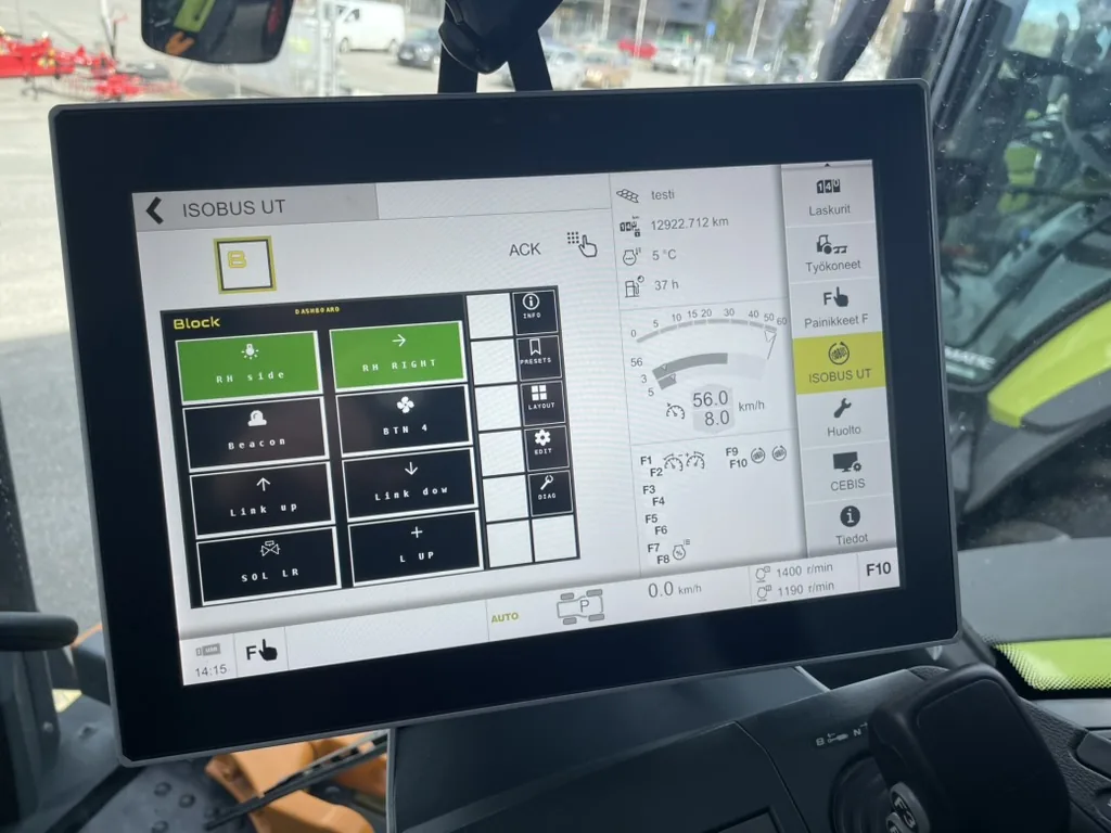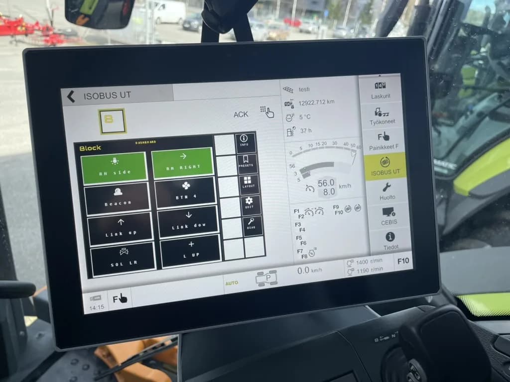
Your tractor already has a screen, a joystick, and a standardised bus connecting everything. If you have an implement or accessory that needs switching β hydraulic valves, work lights, solenoids β the Virtual Terminal can switch it without adding a single switch to the cab.
Here's how ISOBUS terminal solutions work, and how to use them to switch a 12V or 24V device from the display already in front of you.
For the technical deep-dive on object pools, mask types, and VT versions, see ISOBUS Virtual Terminal Explained.
What Is an ISOBUS Virtual Terminal?
An ISOBUS Virtual Terminal (VT), sometimes called a Universal Terminal (UT), is the display device inside the tractor cab that renders control interfaces for connected implements. It is defined in ISO 11783-6, part of the broader ISO 11783 standard that governs all ISOBUS communication.
The "virtual" part matters. Unlike a proprietary display locked to one brand's equipment, a VT is a general-purpose renderer. An implement sends its screen layout β a package called an object pool β across the CAN bus, and the terminal displays it. Any ISOBUS implement can appear on any ISOBUS tractor's screen, regardless of who made either one.
One display, one bus, any implement.
VT vs. UT: Is There a Difference?
In practice, the terms are used interchangeably. The ISO standard uses "Virtual Terminal." The AEF (Agricultural Industry Electronics Foundation) certification programme uses "Universal Terminal." Both refer to the same function: a tractor-side display that renders implement interfaces over ISOBUS. When you see "UT certified" on a tractor spec sheet, it means the same thing as "ISOBUS VT."
Tractor manufacturers use their own trade names for the display. John Deere calls it the CommandCenter; Fendt uses Vario Terminal; Case IH runs AFS Pro 700; New Holland ships IntelliView; Valtra uses SmartTouch; CLAAS runs CEBIS; Massey Ferguson has Datatronic. All of them are ISOBUS Virtual Terminals β they render implement object pools defined in ISO 11783-6 the same way. The trade name is branding; the underlying VT function is the standard.
A Short History: Why the Standard Exists
Before ISOBUS, implement control was proprietary. Each manufacturer shipped their own display, their own connector, their own protocol. An operator running a John Deere tractor with a Kverneland spreader and a Horsch drill needed three separate control units in the cab, each with its own screen and wiring. That is what ISOBUS was built to fix.
ISO 11783 β the formal standard behind ISOBUS β was ratified across the 1990s and 2000s, with volume adoption arriving on mainstream tractors from roughly 2005 onwards. The Virtual Terminal portion (ISO 11783-6) is what made the interface side universal: the implement describes its own screen, the tractor renders it, and neither needs to know anything proprietary about the other.
The result for operators: one screen, one set of buttons, any implement that speaks the standard.
Why Operators End Up Needing a VT Solution
The most common trigger is a new implement that has ISOBUS control but the tractor lacks a working VT, or has a very old VT 3 screen that struggles with modern interfaces. A second trigger is the accumulation of aftermarket switch panels β one added for lighting, another for a hydraulic function, a third for a pump β until the cab looks like a radio switchboard. Replacing all of that with ISOBUS relay outputs on the existing screen is the cleaner option.
Older tractors with good mechanical specs but limited electronics are another case. Adding an aftermarket VT gives the tractor a control interface for any ISOBUS implement, extending the machine's useful life without a fleet replacement.
How ISOBUS Terminal Communication Works
When you connect an implement and power up, it claims a unique address on the CAN bus, uploads its object pool (the complete description of what goes on screen) to the Virtual Terminal, and starts exchanging messages with the display. Simple implements like a relay module are visible in around 10 seconds on first connection; subsequent connections are faster because the VT caches the pool. From there, every button press follows the same loop: operator taps the VT, terminal sends a CAN message, implement responds, terminal updates the display.
For the protocol-level walkthrough β object pool structure, data and alarm masks, soft-key masks, VT 3/4/5/6 versions β see ISOBUS Virtual Terminal Explained.
AUX-N: Physical Button Control
The Virtual Terminal handles on-screen soft key control. AUX-N (Auxiliary Input Type N, defined in ISO 11783-6) extends this to the tractor's physical inputs β joystick buttons, armrest switches, thumbwheels.
With AUX-N, you assign implement functions to physical buttons. Press a joystick trigger and it activates a relay, just as if you had tapped a soft key on the VT screen. Critically, AUX-N assignments work regardless of which implement's screen is currently displayed β your button assignments are always active.
See the ISOBUS AUX-N Complete Guide for full details on setting up button assignments.
Key Capabilities of ISOBUS Terminal Solutions
Soft Key Control
Soft keys are the programmable buttons along the edges of the VT screen. Each implement defines what its soft keys do for each screen. One press turns a relay on; another press navigates to a settings screen. The labels change depending on which screen is active, so the terminal always shows you exactly what each key does.
What this looks like in practice with a relay module: the main screen shows eight channel tiles β CH1 through CH8 β each with a label you set (DIVERTER, R REAR, LIGHTS, and so on). Each tile acts as a soft key. One press toggles the channel. The tile colour changes to confirm the state. No sub-menu, no confirmation dialogue β just press, relay switches.
Multi-Implement Management
Multiple implements can be connected to the ISOBUS network simultaneously. The VT displays one at a time; you switch between them using the working set selector. Each implement's AUX-N button assignments stay active even when you're viewing a different implement's screen.
Persistent Configuration
Your AUX-N button assignments are stored in the tractor, not the implement. Disconnect and reconnect the implement, and the tractor reloads your saved layout automatically. Move the implement to a different tractor and you set it up once on that tractor β it remembers from then on.
Alarm and Status Handling
When an implement detects a fault or warning, it triggers an alarm mask on the VT. The display interrupts the current view and shows the alarm details. This gives you implement status at a glance without polling a separate monitor.
Alarms have priority levels. A critical alarm β say, a section valve failing to respond β pushes to the front of the display immediately. An informational status change appears less intrusively. Either way, the notification arrives on the screen already in front of you.
What You Can Control with ISOBUS Terminal Solutions
If a device runs on 12V or 24V and needs switching, a VT-controlled relay module can handle it. Common applications:
| Category | Examples |
|---|---|
| Hydraulic control | Diverter valves, section valves, lock valves, hydraulic solenoid valves |
| Lighting | Work lights (front, rear, side), beacons, warning lights, implement lighting |
| Solenoids | Proportional valves, on/off solenoids, electric actuators |
| Accessories | Fans, pumps, electric motors, horns, heating elements |
The relay handles the electrical load. ISOBUS provides the control signal. This separation is what makes it safe and flexible β high currents never pass through the ISOBUS network itself.
For a practical example of controlling work lights this way, see How to Install Work Lights Using ISOBUS and AUX-N.
Load Current: What Fits on a Relay Channel
Each relay channel handles up to 10A. That covers most common agricultural loads: LED work light bars, beacon lights, solenoid valves, small pumps, and electric actuators typically draw well under 10A each.
For loads that exceed 10A β large halogen work lights, high-draw hydraulic solenoids on high-pressure manifolds, motor-driven equipment β the relay channel still controls the switching, but through an external contactor rated for the actual load. The relay triggers the contactor coil (low current), the contactor switches the main load (high current). This is standard practice for relay-based control and does not require any changes to how ISOBUS Block is set up.
Section Control and ISOBUS Terminals
Section control β switching implement sections on and off based on GPS position β is one of the main reasons operators run ISOBUS terminal solutions on sprayers, seeders, and spreaders. The standard is called TC-SC (Task Controller β Section Control), defined in ISO 11783-10.
How TC-SC Works
On a machine set up for it, the chain runs like this:
- The tractor's GPS receiver knows its exact position in the field.
- The Task Controller reads the prescription map (or the field boundary) and decides which sections should be active.
- TC-SC sends on/off commands over the ISOBUS bus to the implement's section-control system.
- That system switches the section valves, opening or closing each nozzle feed.
This is automatic, map-driven control. It lives in the tractor's Task Controller and an implement that speaks TC-SC.
Where ISOBUS Block Fits
ISOBUS Block does not do automated GPS section control. It is not a Task Controller client and does not receive TC-SC commands β it is a relay module for manual switching from the tractor's own buttons.
In practice: assign each section's valve to a joystick or armrest button and switch sections by hand as you drive. That covers a lot of real work β turning boom sections on and off at the headland, shutting a section off over a ditch β without a GPS prescription. If you need fully automatic, map-driven section control, that calls for a TC-SCβcapable system, which is a different category from a relay module.
Choosing a VT for Your Workflow
If your tractor has a working ISOBUS Virtual Terminal already, you use it. But when you're choosing a terminal β buying an aftermarket unit, speccing a new tractor, or evaluating what a second machine needs β the version and capability matter.
VT 3 vs. VT 4/5 vs. VT 6
| VT Version | Minimum Display Size[^1] | Colors | Practical Implication |
|---|---|---|---|
| VT 3 | 200Γ200 px | 16 | Works for basic relay control; limited graphics |
| VT 4 | 480Γ480 px | 256 | The mainstream workhorse; most implements target this |
| VT 5 | 480Γ480 px + | 256+ | Incremental over VT 4; most VT 4 pools display correctly |
| VT 6 | 800Γ600 px + | 65,536 | Full-colour, larger screen; more complex interfaces |
[^1]: Minimum addressable pixels per ISO 11783-6. Physical screen size and native resolution vary by tractor manufacturer; the VT scales implement interfaces to fit its display.
For relay and valve switching, VT 3 is functional. The interface is small but usable. If you are also running precision farming implements with detailed maps and multi-screen interfaces, VT 4 or above is the practical floor.
A relay module like ISOBUS Block automatically detects the connected VT version and uploads the appropriate object pool. You do not need a VT 6 terminal to use it.
OEM Terminal vs. Aftermarket Display
OEM terminals are the ones that came with the tractor. They tend to be well-integrated with the tractor's other systems β the Valtra SmartTouch, for example, controls both tractor functions and ISOBUS implements from the same interface. The downside is you get what came with the machine.
Aftermarket ISOBUS terminals from MΓΌller Elektronik, Reichhardt, Topcon, and others are add-on displays that plug into the tractor's in-cab ISOBUS connector and provide full VT functionality. They are the practical option when:
- The tractor has no VT (older machine with just a CAN bus)
- The existing VT is VT 3 and you need VT 4+ for modern implements
- You want a second display for an additional implement without switching working sets on the main screen
Aftermarket terminals connect to the in-cab ISOBUS connector. Once plugged in, any ISOBUS implement appears on them exactly as it would on an OEM terminal. No special configuration for the implement β it just sees a VT and uploads its pool.
Retrofitting vs. New Purchase
Not every machine warrants a full fleet replacement just to gain ISOBUS terminal functionality. The honest decision factors:
When Retrofitting Makes Sense
- The tractor is mechanically sound and will work for several more seasons. The retrofit cost is a small fraction of a new machine β and the tractor has years of useful life left.
- You run multiple ISOBUS implements that all need control from the same seat. An aftermarket VT turns a non-ISOBUS tractor into a capable host for relay modules, ISOBUS spreaders, precision seeders, and more.
- You have a fleet of similar machines where one or two lack VT. Retrofitting those units makes the whole fleet consistent β same operator workflow, same button assignments.
- The alternative is adding multiple aftermarket switch panels. A single aftermarket VT and a relay module replaces several separate controllers while giving you cleaner integration.
When to Wait for the Next Machine
- The tractor is near end of life and a replacement is already in the budget within a year or two. The retrofit payback period won't close.
- The implements you need to run require TC-SC or GPS section control with features beyond a simple relay module. In that case, the depth of VT integration on a new tractor may be worth waiting for.
- The existing cab electronics are already failing. An aftermarket VT on a deteriorating platform adds complexity without solving the underlying reliability problem.
The practical middle ground: adding an aftermarket terminal for relay control only is a single-cable installation into the in-cab ISOBUS connector. Check your tractor manufacturer's policy on aftermarket ISOBUS devices β dealer activation and warranty impact vary by brand and market.
How ISOBUS Block Fits Into This Picture
ISOBUS Block is an 8-channel relay module purpose-built for ISOBUS terminal solutions. It connects to your tractor's ISOBUS network, uploads its interface to the Virtual Terminal, and provides eight independent relay outputs you can switch from the tractor's display. For a full introduction to the product, see Introducing ISOBUS Block.
VT Interface
Once connected, ISOBUS Block appears on the VT as a working set. The main screen shows the state of all eight relay channels at a glance β active or inactive. Soft keys let you toggle each channel with one press. No menus, no sub-screens needed for basic operation.
The module detects your VT version automatically and uploads the appropriate object pool. It works with VT 3, 4, 5, and 6 terminals.
AUX-N Integration
ISOBUS Block provides eight AUX-N boolean functions β one per relay channel. Assign any of them to a joystick button, armrest switch, or other tractor input through your tractor's AUX-N menu. From that point, the physical button directly activates the relay, even while you're viewing a different implement on the VT screen.
Grouped Outputs
One input can switch multiple relay channels at once. Example: one joystick button activates both a diverter valve solenoid and the work light on the attachment β in sync, with a single press. On toggle-switch wiring this needs a second relay and a diode; here it is one line in the VT setup.
Toggle and Momentary Modes
Each channel is set independently:
- Toggle mode: Press once to turn on, press again to turn off. Use this for work lights and continuous loads.
- Momentary mode: Active only while the button is held. Use this for hydraulic valves and temporary functions.
Set the mode from the VT screen β no laptop or external software needed.
CABIN vs. IMPLEMENT: Choosing the Right Kit
ISOBUS Block ships in three tiers. The bare module is for integrators who build their own harness. Most operators choose between CABIN and IMPLEMENT, and the deciding factor is where the module needs to live.
CABIN (β¬1,090) includes the module plus a 1.8 m pre-built harness. The harness runs from the module to the tractor's in-cab ISOBUS connector. Mount the module inside the cab β on a DIN rail, behind the seat, in a side panel β plug both ends of the harness, wire your loads to the relay terminals, assign buttons. Power and CAN signals both travel through the single ISOBUS connection.
CABIN is the right choice when the loads you are switching are reachable from in-cab wiring, you want the module visible for checking status, and the setup is semi-permanent in a dry location.
IMPLEMENT (β¬1,590) mounts the module inside an IP65 weatherproof enclosure. The tractor-side lead terminates in a pre-wired ISOBUS connector that plugs into the tractor's rear external ISOBUS connector. The implement side provides 8 flying leads, each with a 2-pin Deutsch connector, one per relay channel. Bolt the enclosure to the implement, plug in the tractor lead, mate the Deutsch connectors to your loads, assign buttons.
IMPLEMENT is the right choice when the module rides on the implement behind the tractor β a trailed sprayer, a mounted spreader, a rear attachment with multiple solenoids β and the installation environment is wet, dusty, or exposed to weather.
Concrete example β rear sprayer with four section valves: Bolt the IMPLEMENT enclosure to the sprayer chassis. Plug the pre-terminated ISOBUS lead into the rear external connector on the tractor. Mate each Deutsch flying lead to a section solenoid. Assign CH1βCH4 to joystick buttons. Each section now switches from the armrest, by hand as you drive. (For automatic GPS section control you'd need a TC-SC system β that's beyond a relay module.)
Concrete example β front loader with third function and working light: Mount the CABIN module inside the tractor cab. Run relay terminal leads from CH1 to the diverter valve solenoid on the loader and from CH2 to the work light on the bucket. Group CH1 and CH2 to a single joystick button. One press: the diverter valve opens and the light comes on. Press again: both off. Everything switches through the existing ISOBUS network with no additional switch gear in the cab.
Technical Specifications
| Parameter | Value |
|---|---|
| Relay channels | 8 |
| Current per channel | 10A max |
| Supply voltage | 7-36V DC (12V and 24V systems) |
| Operating temperature | β30 Β°C to +50 Β°C |
| Communication | ISOBUS CAN, 250 kbit/s |
| AUX-N functions | 8 (one per relay channel) |
| Mounting | DIN rail |
| Warranty | 5 years |
| Price (module only) | EUR 980 |
For wiring details, the ISOBUS Connector Pinout Guide covers the 9-pin connector and wire assignments you need for connecting to the tractor's ISOBUS socket.
Setting Up an ISOBUS Terminal Solution: Step by Step
Here is the practical sequence for getting a relay module working through your VT. For the full three-layer view of ISOBUS implement control setup β VT, AUX-N, and the module on the implement side β that walkthrough covers the standard layer by layer.
- Wire your devices to the relay module terminals (COM, NO per channel).
- Connect the module to the tractor's ISOBUS socket β CAN_H, CAN_L, power, and ground.
- Power up and wait for the module to appear on the Virtual Terminal (around 10 seconds on first connection; faster on subsequent connections because the VT caches the pool).
- Open the AUX-N menu on your tractor and assign relay functions to your preferred buttons.
- Set each channel on the VT: toggle or momentary mode, grouped outputs if needed.
- Test from both the VT soft keys and your assigned physical buttons.
The tractor stores your AUX-N assignments. The module stores your channel configuration. Both persist across power cycles.
Inline Troubleshooting
If the module does not appear on the VT after power-up: check that the ISOBUS connector is fully seated and that the CAN bus has correct termination (60 ohms between CAN_H and CAN_L at the connector). A missing or double terminator is the most common cause of a missing working set.
If the module appears but AUX-N functions are not visible in the tractor's assignment menu: confirm the implement has fully loaded its object pool on the VT first. Some tractors require the working set to be selected and displayed at least once before AUX-N functions register. A power cycle after first connection resolves this on most platforms.
If a channel activates on the VT soft key but not from the assigned AUX-N button: verify the assignment is saved (exit and re-enter the AUX-N menu). Check that the tractor's AUX-N input is functioning by confirming other assigned functions respond to the same button.
For deeper troubleshooting β CAN bus faults, address conflicts, object pool cache issues β the ISOBUS Troubleshooting Guide covers the most common causes in detail. For in-cab connector wiring questions, the in-cab ISOBUS connector pinout guide has the specific pin assignments.
Frequently Asked Questions
What is the difference between a Virtual Terminal and a Universal Terminal in ISOBUS?
They refer to the same thing. The ISO 11783 standard uses "Virtual Terminal" (VT). The AEF industry certification uses "Universal Terminal" (UT). Both describe the tractor-side display that renders implement interfaces over the ISOBUS CAN bus. A tractor described as "UT certified" has a VT-compliant display.
What are ISOBUS terminal solutions used for?
They let you control implements and accessories from the tractor's existing screen and buttons, without adding aftermarket switches to the cab. Common uses: switching hydraulic solenoid valves, turning work lights on and off, running section control, and switching any 12V or 24V device through a relay module.
Do I need a separate display for an ISOBUS relay module?
No. The relay module uploads its interface to the tractor's existing Virtual Terminal. You use the tractor screen that is already installed. If your tractor has ISOBUS VT capability, no additional display hardware is required.
Which tractors are compatible with ISOBUS terminal solutions?
Any tractor with an ISOBUS-certified Virtual Terminal is compatible. This covers most major brands from roughly 2010β2015 onwards: John Deere, Fendt, Case IH, New Holland, Massey Ferguson, Claas, Valtra, Deutz-Fahr, Kubota, and others. For button assignment via joystick and armrest controls, the tractor also needs AUX-N support β check your tractor's spec sheet to confirm. For a brand-by-brand compatibility breakdown, see the ISOBUS Compatibility Guide.
How many devices can I control from one ISOBUS terminal?
Multiple implements can be connected to the ISOBUS network simultaneously. The VT displays one implement at a time, but AUX-N button assignments work for all connected implements regardless of which one is on screen. With an 8-channel relay module, you have eight independently controllable outputs from a single device.
What VT version do I need for an ISOBUS relay module?
Any Virtual Terminal from version 3 upward. VT 3 covers most ISOBUS tractors made after around 2013 and handles colour, standard soft-key icons, and the object types used by a relay interface. ISOBUS Block works with VT 3, 4, 5, and 6 terminals β no VT 6 tractor required.
Can I add a Virtual Terminal to a tractor that doesn't have one?
Yes. Aftermarket ISOBUS displays from MΓΌller Elektronik, Reichhardt, Topcon, and others plug into the tractor's in-cab ISOBUS connector and add full VT functionality. Once connected, any ISOBUS implement, including an 8-channel relay module, appears on the aftermarket display the same way it would on an OEM terminal.
How does section control work over ISOBUS?
Section control uses TC-SC (Task Controller β Section Control), defined in ISO 11783-10. The tractor's task controller reads a GPS prescription map, decides which sections should be active at each moment, and sends on/off commands over the ISOBUS bus to a TC-SCβcapable implement system, which executes them. ISOBUS Block isn't a section controller β it gives you manual switching of sections from buttons, not automatic GPS control. For the full breakdown, see Section Control and ISOBUS Terminals above.
Do all ISOBUS tractors have a Virtual Terminal built in?
Most do, but not all. Tractors with a full ISOBUS armrest generally include a VT 3+ display in the cab. Older machines with only ISOBUS implement control β no cab-side VT β need an aftermarket Virtual Terminal to run any ISOBUS implement, including a relay module. The ISOBUS Compatibility Guide has the brand-by-brand breakdown.
Will an older tractor with only a basic ISOBUS connection work?
If the tractor has a working ISOBUS VT (even VT 3), it will work for relay control. The ISOBUS Block object pool adapts to VT version automatically. If the tractor has ISOBUS wiring but no VT β common on some older entry-level models β add an aftermarket terminal and it will work from that display.
What is the difference between a VT and an aftermarket rate controller?
A Virtual Terminal is a general-purpose display that renders whatever interface a connected implement sends. An aftermarket rate controller is a purpose-built device for controlling application rate β it typically has its own proprietary screen and logic, and may or may not speak ISOBUS. If it does speak ISOBUS, it appears on the tractor's VT. If it does not, it runs as a standalone unit. Most modern precision application controllers are ISOBUS-based and appear on the VT alongside relay modules and other implements.
Can I use ISOBUS without a tractor screen at all?
Not usefully. AUX-N button assignments require a VT for initial setup, and you lose on-screen control and status without one. The practical minimum is a VT for first-time configuration; after that, physical buttons operate the assigned relay channels on their own. If the tractor lacks a VT entirely, an aftermarket display is the proper fix.
Do I need a separate ISOBUS licence or subscription?
No. ISOBUS is an open standard. Connecting an ISOBUS implement to an ISOBUS tractor does not require licences or subscriptions. Some tractor manufacturers offer optional precision farming software packages through subscription, but basic VT and AUX-N functionality β everything needed for relay control β is part of the standard tractor feature set.
What happens if the tractor's VT fails mid-job?
The relay module keeps its last state β outputs that were on stay on, outputs that were off stay off. AUX-N inputs continue to work as long as the tractor's input hardware is functioning, because the physical button-to-function association is handled at the tractor level. What you lose is the on-screen status view and the ability to change toggle/momentary settings. For a relay controlling work lights or a solenoid valve mid-pass, the practical impact is minimal: press the button, check the physical load for confirmation.
How do I tell if my tractor has VT enabled vs. just CAN bus wiring?
Navigate to the tractor's ISOBUS settings menu (location varies by brand and model). If you see a working set selector or an ISOBUS device list, VT is active. If you have an ISOBUS connector but see no VT menu, the tractor may have the wiring but VT disabled β a common situation on some John Deere models that need dealer-enabled ISOBUS activation. Check your tractor manual or contact the dealer to confirm. The physical presence of the 9-pin ISOBUS socket at the rear does not guarantee VT is running.
Need an ISOBUS relay module for controlling solenoids, work lights, or hydraulic valves? ISOBUS Block provides 8 relay outputs controlled directly from your tractor's Virtual Terminal display. For a step-by-step walkthrough of the full setup β wiring any 12V or 24V device through the relay module and assigning buttons β see Control Any Device from Your ISOBUS Terminal. Quick questions on kit selection, installation, and AUX-N setup are answered on the FAQ page.