ISO 11783 is the standard behind ISOBUS, the reason a sprayer from one brand shows its controls on a tractor terminal from another. It is not one document. It is 14 parts, each covering one layer, from the plug at the back of the tractor to the file a farm office imports after a day of spraying. This page tells you what each part covers and which ones matter for the work you do.
ISO 11783 parts at a glance
| Part | Name | What it means for you |
|---|---|---|
| 1 | General standard for mobile data communication | The map of everything else |
| 2 | Physical layer | Plugs, cables, termination, pinouts |
| 3 | Data link layer | How messages cross the wire |
| 4 | Network layer | Linking separate bus segments together |
| 5 | Network management | How devices get an address |
| 6 | Virtual terminal | Implement screens and joystick buttons |
| 7 | Implement messages application layer | Speed, PTO, hitch, lighting data |
| 8 | Power train messages | Engine and transmission data |
| 9 | Tractor ECU | What the tractor tells implements |
| 10 | Task controller and management information system data interchange | Job records, maps, section control |
| 11 | Mobile data element dictionary | Shared meaning for logged values |
| 12 | Diagnostics services | Fault codes and ECU identification |
| 13 | File server | Shared storage on the bus |
| 14 | Sequence control | Record and replay headland routines |
The 14 parts of ISO 11783, one by one
Part 1: General standard
Part 1 is the entry point. It sets out how the standard is structured, how the layers relate to each other, and the terms and definitions the other parts use. Nobody wires anything from Part 1, but it is where the vocabulary comes from.
Who cares: manufacturers, and anyone writing a specification.
Part 2: Physical layer
Part 2 is the hardware. It defines the bus cable and signaling, the 250 kbit/s bit rate, and the two 9-pin connectors: the rear external ISOBUS connector on the back (or front) of the tractor and the in-cab connector next to the seat. It also covers the terminating bias circuit (TBC), which ends the bus correctly at each physical end. Pin tables for both sockets are in the ISOBUS connector pinout guide, and termination has its own page: ISOBUS terminator and TBC explained.
Who cares: installers, workshops, anyone building a cable.
Part 3: Data link layer
Part 3 defines how messages are packed and sent. ISOBUS uses CAN 2.0B with 29-bit identifiers. Each message type has a parameter group number (PGN) that tells every receiver what the data is. Messages longer than eight bytes, such as an implement uploading its screens, are split up and reassembled with the transport protocols defined here. This part follows SAE J1939 closely. ISOBUS vs CAN bus vs J1939 sets the three side by side.
Who cares: manufacturers and anyone reading a CAN trace.
Part 4: Network layer
A tractor can run more than one CAN segment, for example its own internal bus and the implement bus that runs out to the rear socket. Part 4 defines the network interconnection unit: the device that links segments and decides which messages pass between them, working as a bridge, router or gateway. On most tractors you never see it.
Who cares: tractor manufacturers and builders of large multi-segment implements.
Part 5: Network management
Every device on the bus needs an address, and Part 5 covers how it gets one. Each device carries a 64-bit NAME that describes what it is and who made it. On power-up it claims an address. If two devices want the same one, the NAME decides who keeps it. The tractor also uses the NAME to recognize an implement, which is how AUX-N button assignments survive unplugging.
Who cares: manufacturers, and workshops chasing a device that never appears.
Part 6: Virtual Terminal
The part most operators meet every day. The implement uploads an object pool (its screens, buttons, icons and values) and the terminal draws it. Part 6 also covers auxiliary control, both the older AUX-O and the current AUX-N, which puts implement functions on the tractor's joystick and armrest buttons. The VT version a terminal reports refers to this part. More in the Virtual Terminal guide and the AUX-N complete guide.
Who cares: everyone.
Part 7: Implement messages application layer
Part 7 lists the everyday messages tractors and implements share: wheel-based and ground-based speed, PTO speed, front and rear hitch position, lighting commands, auxiliary valve messages, and the language and unit settings a terminal uses. A spreader holding its rate from ground speed is reading a Part 7 message.
Who cares: manufacturers. Operators notice it when a speed or hitch signal goes missing.
Part 8: Power train messages
Part 8 covers engine and transmission messages, carried over from the J1939 world. It matters mostly inside the tractor. What an implement needs about the tractor usually comes through Parts 7 and 9.
Who cares: tractor manufacturers. Most others can skip it.
Part 9: Tractor ECU
Part 9 defines the tractor ECU (TECU), the tractor's own node on the implement bus. It reports the tractor's state to the implement and handles power to the implement's electronics. The standard sorts TECUs into classes. Class 1 sends the basics, such as speed, PTO and hitch position. Class 2 adds a fuller set of measurements. Class 3 accepts commands from the implement, for example to move the hitch. The implement side is in the ISOBUS ECU guide.
Who cares: manufacturers, and buyers of implements that need tractor data.
Part 10: Task Controller
Part 10 covers the Task Controller and data exchange with farm software. The implement sends the Task Controller a description of itself (sections, geometry, what it can log), and the Task Controller records work and sends commands back. Task data moves between terminal and farm office as ISOXML files. Spec sheets split this into TC-BAS for totals, TC-GEO for position-based records and prescription maps, and TC-SC for automatic section control. See ISOBUS section control explained.
Who cares: operators who document work or run variable rate, and manufacturers.
Part 11: Mobile data element dictionary
When a sprayer logs applied volume, the farm software has to know what that number means. Part 11 is the shared dictionary. Each data item has a data dictionary identifier (DDI) with a defined meaning, unit and resolution. The dictionary is maintained as an online database, so new entries appear without waiting for a new edition.
Who cares: manufacturers and farm software developers.
Part 12: Diagnostics services
Part 12 defines how ECUs report faults and identify themselves. Fault codes follow the J1939 structure: an SPN for what is affected and an FMI for how it failed, split into active and previously active codes. It also covers identifying the ECU and its software, so a service tool knows what it is talking to. Reading the codes is covered in the ISOBUS fault codes guide.
Who cares: workshops, and operators reading a fault on screen.
Part 13: File server
Part 13 defines a file server: a device on the bus with storage that other ECUs can read from and write to. It is often part of the terminal. An ECU without storage of its own can keep files there.
Who cares: manufacturers. Operators only see whether a feature that depends on it works.
Part 14: Sequence control
Part 14 covers recording and replaying a sequence of functions, typically the headland routine: lift the hitch, fold the markers, stop the PTO, then the reverse on the way back in. A sequence control master records and replays the steps, and the tractor and implement functions taking part act as clients. Both machines need to support it.
Who cares: operators who use headland automation, and manufacturers.
Which ISO 11783 parts matter to whom
Operator
Part 6 is the one you use: the implement's screens on your terminal and its functions on your joystick. Part 10 matters if you document work, use prescription maps or want section control. Part 12 is behind the fault codes on your screen.
Farm workshop
Part 2 for cables, pinouts and termination. Part 5 when a device does not show up or two devices clash. Part 12 for fault codes. Part 3 when you put a CAN logger on the bus and need to make sense of the PGNs.
Implement manufacturer
The floor is Parts 2, 3, 5 and 6: connector, messaging, address claiming and a working object pool. Add Part 10 for documentation or section control, Part 7 and Part 9 for tractor data, Part 11 for logged values and Part 12 for diagnostics. The OEM guide to making an implement ISOBUS-ready turns this into a plan.
Where ISOBUS Block fits
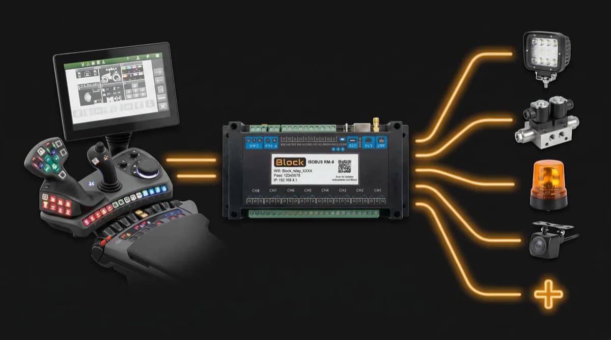
ISOBUS Block uses four parts of the standard. Part 2: it plugs into the in-cab or the external 9-pin ISOBUS connector. Part 3: it talks on the tractor's CAN bus. Part 5: it claims its own address like any other device. Part 6: it uploads its object pool, so its buttons appear on the tractor screen, each switching a relay channel, CH1 to CH8, in TOG or MOM mode, and it publishes AUX-N functions you assign to joystick or armrest buttons.
It is not a Task Controller client. No TC-BAS, no TC-GEO, no TC-SC. A relay channel you switch from the screen is switched by you, not by a map.
Frequently asked questions
What is ISO 11783?
ISO 11783 is the international standard for data communication between tractors, implements and the terminal in the cab. It defines the connector, the CAN network, the Virtual Terminal, the Task Controller and diagnostics.
How many parts does ISO 11783 have?
Fourteen, numbered Part 1 to Part 14. Each part covers one area, such as the physical layer (Part 2), the Virtual Terminal (Part 6) or the Task Controller (Part 10).
What is the difference between ISO 11783 and ISOBUS?
None in substance. ISO 11783 is the formal name of the standard and ISOBUS is the name the industry uses for it. Technical documents use the part numbers.
Which part of ISO 11783 covers the connector?
Part 2, the physical layer. It defines the rear external ISOBUS connector, the in-cab connector, the cable and the bus termination.
Which part of ISO 11783 covers the Virtual Terminal?
Part 6. It defines how an implement uploads its object pool to the terminal and how the terminal draws it. Auxiliary control, including AUX-N joystick assignment, is in Part 6 as well.
Is ISO 11783 based on J1939?
Yes. ISOBUS grew out of SAE J1939, the CAN standard used in trucks and engines. The data link layer, network management and diagnostics follow J1939 closely, which is why fault codes use the same SPN and FMI structure. The agricultural layers, such as the Virtual Terminal and Task Controller, are ISOBUS's own.
Need an ISOBUS relay module for controlling solenoids, work lights, or hydraulic valves? ISOBUS Block provides 8 relay outputs controlled directly from your tractor's Virtual Terminal display.